SBOS921F December 2018 – November 2023 TMP61
PRODUCTION DATA
- 1
- 1 Features
- 2 Applications
- 3 Description
- 4 Device Comparison
- 5 Pin Configuration and Functions
- 6 Specifications
- 7 Detailed Description
- 8 Application and Implementation
- 9 Device and Documentation Support
- 10Revision History
- 11Mechanical, Packaging, and Orderable Information
Package Options
Mechanical Data (Package|Pins)
Thermal pad, mechanical data (Package|Pins)
Orderable Information
3 Description
Get started today with the Thermistor Design Tool, offering complete resistance vs temperature table (R-T table) computation, other helpful methods to derive temperature and example C-code.
The TMP61 linear thermistor offers linearity and consistent sensitivity across temperature to enable simple and accurate methods for temperature conversion. The low power consumption and a small thermal mass of the device minimize self-heating.
With built-in fail-safe behaviors at high temperatures and powerful immunity to environmental variation, these devices are designed for a long lifetime of high performance. The small size of the TMP6 series also allows for close placement to heat sources and quick response times.
Take advantage of benefits over NTC thermistors such as no extra linearization circuitry, minimized calibration, less resistance tolerance variation, larger sensitivity at high temperatures, and simplified conversion methods to save time and memory.
The TMP61 is currently available in a 0402 X1SON package, a 0603 SOT-5X3 package, and a 2-pin through-hole TO-92S package.
| PART NUMBER | PACKAGE(1) | PACKAGE SIZE(2) |
|---|---|---|
| TMP61 | DEC (X1SON, 2) | 1.00 mm × 0.60 mm |
| LPG (TO-92S, 2) | 4.00 mm × 1.52 mm | |
| DYA (SOT-5X3, 2) | 1.60 mm × 0.80 mm |
 Typical Implementation Circuits
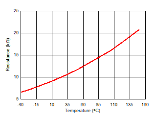
 Typical Resistances vs Ambient Temperature