SPRSP45C March 2020 – April 2024 TMS320F280021 , TMS320F280021-Q1 , TMS320F280023 , TMS320F280023-Q1 , TMS320F280023C , TMS320F280025 , TMS320F280025-Q1 , TMS320F280025C , TMS320F280025C-Q1
PRODUCTION DATA
- 1
- 1 Features
- 2 Applications
- 3 Description
- 4 Device Comparison
- 5 Terminal Configuration and Functions
-
6 Specifications
- 6.1 Absolute Maximum Ratings
- 6.2 ESD Ratings – Commercial
- 6.3 ESD Ratings – Automotive
- 6.4 Recommended Operating Conditions
- Supply Voltages
- 6.5 Power Consumption Summary
- 6.6 Electrical Characteristics
- 6.7 Thermal Resistance Characteristics for PN Package
- 6.8 Thermal Resistance Characteristics for PM Package
- 6.9 Thermal Resistance Characteristics for PT Package
- 6.10 Thermal Design Considerations
- 6.11
System
- 6.11.1 Power Management Module (PMM)
- 6.11.2 Reset Timing
- 6.11.3
Clock Specifications
- 6.11.3.1 Clock Sources
- 6.11.3.2 Clock Frequencies, Requirements, and Characteristics
- 6.11.3.3 Input Clocks and PLLs
- 6.11.3.4 XTAL Oscillator
- 6.11.3.5 Internal Oscillators
- 6.11.4 Flash Parameters
- 6.11.5 RAM Specifications
- 6.11.6 ROM Specifications
- 6.11.7 Emulation/JTAG
- 6.11.8 GPIO Electrical Data and Timing
- 6.11.9 Interrupts
- 6.11.10
Low-Power Modes
- 6.11.10.1 Clock-Gating Low-Power Modes
- 6.11.10.2
Low-Power Mode Wake-up Timing
- 6.11.10.2.1 IDLE Mode Timing Requirements
- 6.11.10.2.2 IDLE Mode Switching Characteristics
- 6.11.10.2.3 IDLE Entry and Exit Timing Diagram
- 6.11.10.2.4 STANDBY Mode Timing Requirements
- 6.11.10.2.5 STANDBY Mode Switching Characteristics
- 6.11.10.2.6 STANDBY Entry and Exit Timing Diagram
- 6.11.10.2.7 HALT Mode Timing Requirements
- 6.11.10.2.8 HALT Mode Switching Characteristics
- 6.11.10.2.9 HALT Entry and Exit Timing Diagram
- 6.12 Analog Peripherals
- 6.13
Control Peripherals
- 6.13.1 Enhanced Pulse Width Modulator (ePWM)
- 6.13.2 High-Resolution Pulse Width Modulator (HRPWM)
- 6.13.3 Enhanced Capture and High-Resolution Capture (eCAP, HRCAP)
- 6.13.4 Enhanced Quadrature Encoder Pulse (eQEP)
- 6.14
Communications Peripherals
- 6.14.1 Controller Area Network (CAN)
- 6.14.2 Inter-Integrated Circuit (I2C)
- 6.14.3 Power Management Bus (PMBus) Interface
- 6.14.4 Serial Communications Interface (SCI)
- 6.14.5 Serial Peripheral Interface (SPI)
- 6.14.6 Local Interconnect Network (LIN)
- 6.14.7 Fast Serial Interface (FSI)
- 6.14.8 Host Interface Controller (HIC)
-
7 Detailed Description
- 7.1 Overview
- 7.2 Functional Block Diagram
- 7.3 Memory
- 7.4 Identification
- 7.5 Bus Architecture – Peripheral Connectivity
- 7.6 C28x Processor
- 7.7 Embedded Real-Time Analysis and Diagnostic (ERAD)
- 7.8 Background CRC-32 (BGCRC)
- 7.9 Direct Memory Access (DMA)
- 7.10 Device Boot Modes
- 7.11 Dual Code Security Module
- 7.12 Watchdog
- 7.13 C28x Timers
- 7.14 Dual-Clock Comparator (DCC)
- 7.15 Configurable Logic Block (CLB)
- 8 Applications, Implementation, and Layout
- 9 Device and Documentation Support
- 10Revision History
- 11Mechanical, Packaging, and Orderable Information
Package Options
Mechanical Data (Package|Pins)
Thermal pad, mechanical data (Package|Pins)
Orderable Information
6.11.4 Flash Parameters
Table 6-5 lists the minimum required Flash wait states with different clock sources and frequencies. Wait state is the value set in register FRDCNTL[RWAIT].
| CPUCLK (MHz) | EXTERNAL OSCILLATOR OR CRYSTAL | INTOSC1 OR INTOSC2 | ||
|---|---|---|---|---|
| NORMAL OPERATION | BANK OR PUMP SLEEP(1) | NORMAL OPERATION | BANK OR PUMP SLEEP(1) | |
| 97 < CPUCLK ≤ 100 | 4 | 4 | 5 | |
| 80 < CPUCLK ≤ 97 | 4 | |||
| 77 < CPUCLK ≤ 80 | 3 | 3 | 4 | |
| 60 < CPUCLK ≤ 77 | 3 | |||
| 58 < CPUCLK ≤ 60 | 2 | 2 | 3 | |
| 40 < CPUCLK ≤ 58 | 2 | |||
| 38 < CPUCLK ≤ 40 | 1 | 1 | 2 | |
| 20 < CPUCLK ≤ 38 | 1 | |||
| 19 < CPUCLK ≤ 20 | 0 | 0 | 1 | |
| CPUCLK ≤ 19 | 0 | |||
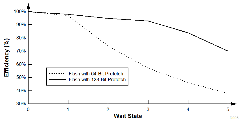
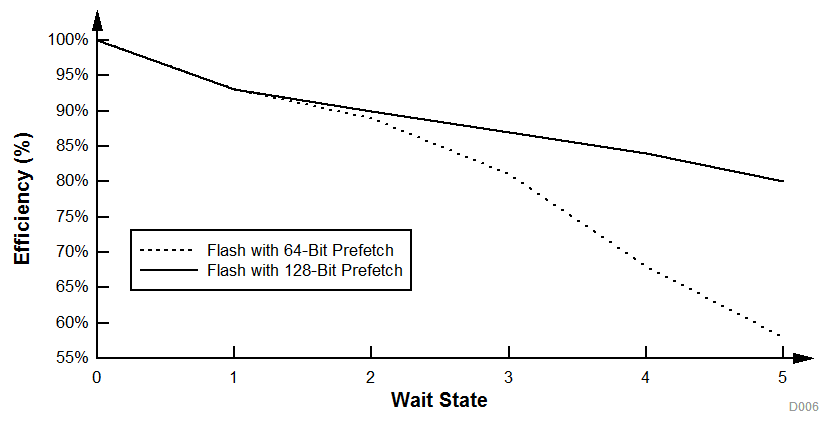
The F28002x devices have an improved 128-bit prefetch buffer that provides high flash code execution efficiency across wait states. Figure 6-22 and Figure 6-23 illustrate typical efficiency across wait-state settings compared to previous-generation devices with a 64-bit prefetch buffer. Wait-state execution efficiency with a prefetch buffer will depend on how many branches are present in application software. Two examples of linear code and if-then-else code are provided.
 Figure 6-22 Application Code With Heavy 32-Bit Floating-Point Math Instructions
 Figure 6-23 Application Code With 16-Bit If-Else Instructions
Table 6-6 lists the Flash parameters.
| PARAMETER | MIN | TYP | MAX | UNIT | |
|---|---|---|---|---|---|
| Program Time(1) | 128 data bits + 16 ECC bits | 150 | 300 | µs | |
| 8KB sector | 50 | 100 | ms | ||
| Erase Time(2)(3) at < 25 cycles | 8KB sector | 15 | 56 | ms | |
| Erase Time(2)(3) at 1000 cycles | 8KB sector | 25 | 133 | ms | |
| Erase Time(2)(3) at 2000 cycles | 8KB sector | 30 | 226 | ms | |
| Erase Time(2)(3) at 20K cycles | 8KB sector | 120 | 1026 | ms | |
| Nwec Write/Erase Cycles per sector | 20000 | cycles | |||
| Nwec Write/Erase Cycles for entire Flash (combined all sectors)(4) | 100000 | cycles | |||
| tretention Data retention duration at TJ = 85oC | 20 | years | |||
• Code that uses flash API to program the flash
• Flash API itself
• Flash data to be programmed
In other words, the time indicated in this table is applicable after all the required code/data is available in the device RAM, ready for
programming. The transfer time will significantly vary depending on the speed of the JTAG debug probe used.
Program time calculation is based on programming 144 bits at a time at the specified operating frequency. Program time includes
Program verify by the CPU. The program time does not degrade with write/erase (W/E) cycling, but the erase time does.
Erase time includes Erase verify by the CPU and does not involve any data transfer.
The Main Array flash programming must be aligned to 64-bit address boundaries and each 64-bit word may only be programmed once per write/erase cycle.
The DCSM OTP programming must be aligned to 128-bit address boundaries and each 128-bit word may only be programmed once. The exceptions are:
- The DCSM Zx-LINKPOINTER1 and Zx-LINKPOINTER2 values in the DCSM OTP should be programmed together, and may be programmed 1 bit at a time as required by the DCSM operation.
- The DCSM Zx-LINKPOINTER3 values in the DCSM OTP may be programmed 1 bit at a time on a 64-bit boundary to separate it from Zx-PSWDLOCK, which must only be programmed once.