SPRS945G January 2017 – January 2023 TMS320F280040-Q1 , TMS320F280040C-Q1 , TMS320F280041 , TMS320F280041-Q1 , TMS320F280041C , TMS320F280041C-Q1 , TMS320F280045 , TMS320F280048-Q1 , TMS320F280048C-Q1 , TMS320F280049 , TMS320F280049-Q1 , TMS320F280049C , TMS320F280049C-Q1
PRODUCTION DATA
- 1 Features
- 2 Applications
- 3 Description
- 4 Revision History
- 5 Device Comparison
- 6 Pin Configuration and Functions
-
7 Specifications
- 7.1 Absolute Maximum Ratings
- 7.2 ESD Ratings – Commercial
- 7.3 ESD Ratings – Automotive
- 7.4 Recommended Operating Conditions
- 7.5 Power Consumption Summary
- 7.6 Electrical Characteristics
- 7.7 Thermal Resistance Characteristics
- 7.8 Thermal Design Considerations
- 7.9
System
- 7.9.1
Power Management Module (PMM)
- 7.9.1.1 Introduction
- 7.9.1.2 Overview
- 7.9.1.3 External Components
- 7.9.1.4 Power Sequencing
- 7.9.1.5 Power Management Module Electrical Data and Timing
- 7.9.2 Reset Timing
- 7.9.3
Clock Specifications
- 7.9.3.1 Clock Sources
- 7.9.3.2 Clock Frequencies, Requirements, and Characteristics
- 7.9.3.3 Input Clocks and PLLs
- 7.9.3.4 Crystal (XTAL) Oscillator
- 7.9.3.5 Internal Oscillators
- 7.9.4 Flash Parameters
- 7.9.5 Emulation/JTAG
- 7.9.6 GPIO Electrical Data and Timing
- 7.9.7 Interrupts
- 7.9.8 Low-Power Modes
- 7.9.1
Power Management Module (PMM)
- 7.10 Analog Peripherals
- 7.11
Control Peripherals
- 7.11.1 Enhanced Capture (eCAP)
- 7.11.2 High-Resolution Capture Submodule (HRCAP6–HRCAP7)
- 7.11.3 Enhanced Pulse Width Modulator (ePWM)
- 7.11.4 High-Resolution Pulse Width Modulator (HRPWM)
- 7.11.5 Enhanced Quadrature Encoder Pulse (eQEP)
- 7.11.6 Sigma-Delta Filter Module (SDFM)
- 7.12
Communications Peripherals
- 7.12.1 Controller Area Network (CAN)
- 7.12.2 Inter-Integrated Circuit (I2C)
- 7.12.3 Power Management Bus (PMBus) Interface
- 7.12.4 Serial Communications Interface (SCI)
- 7.12.5 Serial Peripheral Interface (SPI)
- 7.12.6 Local Interconnect Network (LIN)
- 7.12.7 Fast Serial Interface (FSI)
-
8 Detailed Description
- 8.1 Overview
- 8.2 Functional Block Diagram
- 8.3 Memory
- 8.4 Identification
- 8.5 Bus Architecture – Peripheral Connectivity
- 8.6 C28x Processor
- 8.7 Control Law Accelerator (CLA)
- 8.8 Direct Memory Access (DMA)
- 8.9 Boot ROM and Peripheral Booting
- 8.10 Dual Code Security Module
- 8.11 Watchdog
- 8.12 Configurable Logic Block (CLB)
- 8.13 Functional Safety
- 9 Applications, Implementation, and Layout
- 10Device and Documentation Support
- 11Mechanical, Packaging, and Orderable Information
Package Options
Mechanical Data (Package|Pins)
- PM|64
Thermal pad, mechanical data (Package|Pins)
Orderable Information
7.9.1.2.6 Internal 1.2-V Switching Regulator (DC-DC)
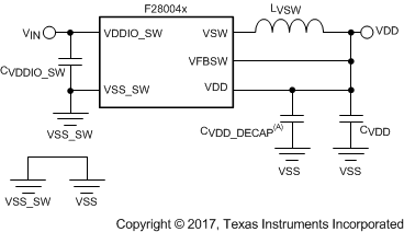
The internal DC-DC regulator offers increased efficiency over the LDO for converting 3.3 V to 1.2 V. The internal DC-DC regulator is supplied by the VDDIO_SW pin and generates the 1.2 V required to power the VDD pins. To use the internal switching regulator, the core domain must power up initially using the internal LDO VREG supply (tie the VREGENZ pin low to VSS) and then transition to the DC-DC regulator through application software by setting the DCDCEN bit in the DCDCCTL register. VREGENZ must still be kept low after transition since it controls both the DC-DC and LDO. Tying VREGENZ high disables both the DC-DC and LDO. The DC-DC regulator also requires external components (inductor, input capacitance, and output capacitance). The output of internal DC-DC regulator is not internally fed to the VDD rail and requires an external connection. Figure 7-8 shows the schematic implementation.

The VDDIO_SW supply pin (VIN) requires a 3.3-V level voltage. A total input capacitance (CVDDIO_SW) of 20 µF is required on VDDIO_SW. Due to the capacitor specification requirements detailed in Table 7-2, two parallel 10-µF capacitors in parallel is the recommended configuration. Decoupling capacitors of 100 nF should also be placed on each VDD pin as close to the device as possible.
| VALUE AND VARIATION | VALUE AT SATURATION | DCR | RATED CURRENT | SATURATION CURRENT | TEMPERATURE |
|---|---|---|---|---|---|
| 2.2 µH ± 20% | 1.54 µH ± 20% | 80 mΩ ± 25% | >1000 mA | >600 mA | –40°C to 125°C |
| VALUE AND VARIATION AT 0 V | VALUE AT 1.2 V | VALUE AT 125°C | ESR | RATED VOLTAGE | TEMPERATURE |
|---|---|---|---|---|---|
| 10 µF ± 20% | 10 µF ± 20% | 8 µF ± 20% | <10 mΩ | 4 V or 6.3 V | –40°C to 125°C |
| COMPONENT | MIN | NOM | MAX | UNIT | NOTES |
|---|---|---|---|---|---|
| Inductor | 1.76 | 2.2 | 2.64 | µH | 20% variance |
| Input capacitor | 8 | 10 | 12 | µF | 20% varaince, two such capacitors in parallel |
| Output capacitor | 8 | 10 | 12 | µF | 20% varaince, two such capacitors in parallel |