SPRS902K October 2014 – February 2024 TMS320F28075 , TMS320F28075-Q1 , TMS320F28076
PRODUCTION DATA
- 1
- 1 Features
- 2 Applications
- 3 Description
- 4 Device Comparison
- 5 Pin Configuration and Functions
-
6 Specifications
- 6.1 Absolute Maximum Ratings
- 6.2 ESD Ratings – Commercial
- 6.3 ESD Ratings – Automotive
- 6.4 Recommended Operating Conditions
- 6.5 Power Consumption Summary
- 6.6 Electrical Characteristics
- 6.7 Thermal Resistance Characteristics
- 6.8 Thermal Design Considerations
- 6.9
System
- 6.9.1 Power Management
- 6.9.2 Reset Timing
- 6.9.3
Clock Specifications
- 6.9.3.1 Clock Sources
- 6.9.3.2 Clock Frequencies, Requirements, and Characteristics
- 6.9.3.3 Input Clocks and PLLs
- 6.9.3.4 XTAL Oscillator
- 6.9.3.5 Internal Oscillators
- 6.9.4 Flash Parameters
- 6.9.5 RAM Specifications
- 6.9.6 ROM Specifications
- 6.9.7 Emulation/JTAG
- 6.9.8 GPIO Electrical Data and Timing
- 6.9.9 Interrupts
- 6.9.10
Low-Power Modes
- 6.9.10.1 Clock-Gating Low-Power Modes
- 6.9.10.2 Power-Gating Low-Power Modes
- 6.9.10.3
Low-Power Mode Wakeup Timing
- 6.9.10.3.1 IDLE Mode Timing Requirements
- 6.9.10.3.2 IDLE Mode Switching Characteristics
- 6.9.10.3.3 STANDBY Mode Timing Requirements
- 6.9.10.3.4 STANDBY Mode Switching Characteristics
- 6.9.10.3.5 HALT Mode Timing Requirements
- 6.9.10.3.6 HALT Mode Switching Characteristics
- 6.9.10.3.7 HIBERNATE Mode Timing Requirements
- 6.9.10.3.8 HIBERNATE Mode Switching Characteristics
- 6.9.11 External Memory Interface (EMIF)
- 6.10 Analog Peripherals
- 6.11
Control Peripherals
- 6.11.1 Enhanced Capture (eCAP)
- 6.11.2 Enhanced Pulse Width Modulator (ePWM)
- 6.11.3 Enhanced Quadrature Encoder Pulse (eQEP)
- 6.11.4 High-Resolution Pulse Width Modulator (HRPWM)
- 6.11.5 Sigma-Delta Filter Module (SDFM)
- 6.12
Communications Peripherals
- 6.12.1 Controller Area Network (CAN)
- 6.12.2 Inter-Integrated Circuit (I2C)
- 6.12.3 Multichannel Buffered Serial Port (McBSP)
- 6.12.4 Serial Communications Interface (SCI)
- 6.12.5 Serial Peripheral Interface (SPI)
- 6.12.6 Universal Serial Bus (USB) Controller
-
7 Detailed Description
- 7.1 Overview
- 7.2 Functional Block Diagram
- 7.3 Memory
- 7.4 Identification
- 7.5 Bus Architecture – Peripheral Connectivity
- 7.6 C28x Processor
- 7.7 Control Law Accelerator
- 7.8 Direct Memory Access
- 7.9 Boot ROM and Peripheral Booting
- 7.10 Dual Code Security Module
- 7.11 Timers
- 7.12 Nonmaskable Interrupt With Watchdog Timer (NMIWD)
- 7.13 Watchdog
- 7.14 Configurable Logic Block (CLB)
- 7.15 Functional Safety
-
8 Applications, Implementation, and Layout
- 8.1 Application and Implementation
- 8.2 Key Device Features
- 8.3 Application Information
- 9 Device and Documentation Support
- 10Revision History
- 11Mechanical, Packaging, and Orderable Information
Package Options
Refer to the PDF data sheet for device specific package drawings
Mechanical Data (Package|Pins)
- PZP|100
- PTP|176
Thermal pad, mechanical data (Package|Pins)
Orderable Information
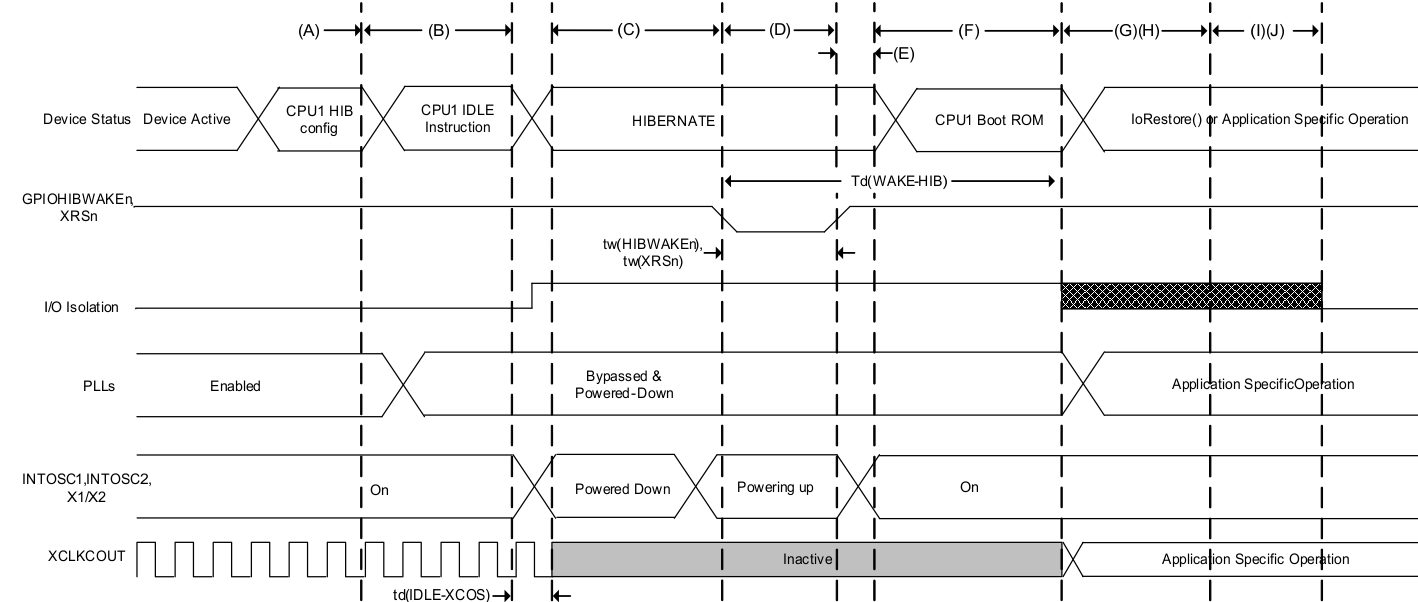
6.9.10.3.8 HIBERNATE Mode Switching Characteristics
over recommended operating conditions (unless otherwise noted)
| PARAMETER | MIN | MAX | UNIT | |
|---|---|---|---|---|
| td(IDLE-XCOS) | Delay time, IDLE instruction executed to XCLKOUT stop | 30tc(SYSCLK) | cycles | |
| td(WAKE-HIB) | Delay time, external wake signal to lORestore function start | 1.5 | ms | |

A. CPU1 does necessary
application-specific context save to M0/M1 memories if required. This includes
GPIO state if using I/O Isolation. Configures the LPMCR register of CPU1 for
HIBERNATE mode. Powers down Flash Pump/Bank, USB-PHY, CMPSS, DAC, and ADC using
their register configurations. The application should also power down the PLL
and peripheral clocks before entering HIBERNATE.
B. IDLE instruction is executed to
put the device into HIBERNATE mode.
C. The device is now in HIBERNATE
mode. If configured, I/O isolation is turned on, M0 and M1 memories are
retained.
CPU1
is powered down. Digital peripherals are powered down. The oscillators,
PLLs, analog peripherals, and Flash are in their software-controlled Low-Power
modes. Dx, LSx, and GSx memories are also powered down, and their memory
contents lost.
D. A falling edge on the
GPIOHIBWAKEn pin will drive the wakeup of the devices clock sources INTOSC1,
INTOSC2, and X1/X2 OSC. The wakeup source must keep the GPIOHIBWAKEn pin low
long enough to ensure full power-up of these clock sources.
E. After the clock sources are
powered up, the GPIOHIBWAKEn must be driven high to trigger the wakeup sequence
of the remainder of the device.
F. The BootROM will then begin to
execute. The BootROM can distinguish a HIBERNATE wakeup by reading the
CPU1.REC.HIBRESETn bit. After the TI OTP trims are loaded, the BootROM code will
branch to the user-defined IoRestore function if it has been configured.
G. At this point, the device is out
of HIBERNATE mode, and the application may continue.
H. The IoRestore function is a
user-defined function where the application may reconfigure GPIO states, disable
I/O isolation, reconfigure the PLL, restore peripheral configurations, or branch
to application code. This is up to the application requirements.
I. If the application has not
branched to application code, the BootROM will continue after completing
IoRestore. It will disable I/O isolation automatically if it was not taken care
of inside of IoRestore.
J. BootROM will then boot as
determined by the HIBBOOTMODE register. Refer to the ROM Code and Peripheral
Booting chapter of the
TMS320F2807x Real-Time
Microcontrollers Technical Reference Manual for more
information.
Figure 6-24 HIBERNATE
Entry and Exit Timing DiagramNote:
- If the IORESTOREADDR is configured as the default value, the BootROM will continue its execution to boot as determined by the HIBBOOTMODE register. Refer to the ROM Code and Peripheral Booting chapter of the TMS320F2807x Real-Time Microcontrollers Technical Reference Manual for more information.
- The user may choose to disable I/O Isolation at any point in the IoRestore function. Regardless if the user has disabled Isolation in the IoRestore function or if IoRestore is not defined, the BootROM will automatically disable isolation before booting as determined by the HIBBOOTMODE register.