SPRS902K October 2014 – February 2024 TMS320F28075 , TMS320F28075-Q1 , TMS320F28076
PRODUCTION DATA
- 1
- 1 Features
- 2 Applications
- 3 Description
- 4 Device Comparison
- 5 Pin Configuration and Functions
-
6 Specifications
- 6.1 Absolute Maximum Ratings
- 6.2 ESD Ratings – Commercial
- 6.3 ESD Ratings – Automotive
- 6.4 Recommended Operating Conditions
- 6.5 Power Consumption Summary
- 6.6 Electrical Characteristics
- 6.7 Thermal Resistance Characteristics
- 6.8 Thermal Design Considerations
- 6.9
System
- 6.9.1 Power Management
- 6.9.2 Reset Timing
- 6.9.3
Clock Specifications
- 6.9.3.1 Clock Sources
- 6.9.3.2 Clock Frequencies, Requirements, and Characteristics
- 6.9.3.3 Input Clocks and PLLs
- 6.9.3.4 XTAL Oscillator
- 6.9.3.5 Internal Oscillators
- 6.9.4 Flash Parameters
- 6.9.5 RAM Specifications
- 6.9.6 ROM Specifications
- 6.9.7 Emulation/JTAG
- 6.9.8 GPIO Electrical Data and Timing
- 6.9.9 Interrupts
- 6.9.10
Low-Power Modes
- 6.9.10.1 Clock-Gating Low-Power Modes
- 6.9.10.2 Power-Gating Low-Power Modes
- 6.9.10.3
Low-Power Mode Wakeup Timing
- 6.9.10.3.1 IDLE Mode Timing Requirements
- 6.9.10.3.2 IDLE Mode Switching Characteristics
- 6.9.10.3.3 STANDBY Mode Timing Requirements
- 6.9.10.3.4 STANDBY Mode Switching Characteristics
- 6.9.10.3.5 HALT Mode Timing Requirements
- 6.9.10.3.6 HALT Mode Switching Characteristics
- 6.9.10.3.7 HIBERNATE Mode Timing Requirements
- 6.9.10.3.8 HIBERNATE Mode Switching Characteristics
- 6.9.11 External Memory Interface (EMIF)
- 6.10 Analog Peripherals
- 6.11
Control Peripherals
- 6.11.1 Enhanced Capture (eCAP)
- 6.11.2 Enhanced Pulse Width Modulator (ePWM)
- 6.11.3 Enhanced Quadrature Encoder Pulse (eQEP)
- 6.11.4 High-Resolution Pulse Width Modulator (HRPWM)
- 6.11.5 Sigma-Delta Filter Module (SDFM)
- 6.12
Communications Peripherals
- 6.12.1 Controller Area Network (CAN)
- 6.12.2 Inter-Integrated Circuit (I2C)
- 6.12.3 Multichannel Buffered Serial Port (McBSP)
- 6.12.4 Serial Communications Interface (SCI)
- 6.12.5 Serial Peripheral Interface (SPI)
- 6.12.6 Universal Serial Bus (USB) Controller
-
7 Detailed Description
- 7.1 Overview
- 7.2 Functional Block Diagram
- 7.3 Memory
- 7.4 Identification
- 7.5 Bus Architecture – Peripheral Connectivity
- 7.6 C28x Processor
- 7.7 Control Law Accelerator
- 7.8 Direct Memory Access
- 7.9 Boot ROM and Peripheral Booting
- 7.10 Dual Code Security Module
- 7.11 Timers
- 7.12 Nonmaskable Interrupt With Watchdog Timer (NMIWD)
- 7.13 Watchdog
- 7.14 Configurable Logic Block (CLB)
- 7.15 Functional Safety
-
8 Applications, Implementation, and Layout
- 8.1 Application and Implementation
- 8.2 Key Device Features
- 8.3 Application Information
- 9 Device and Documentation Support
- 10Revision History
- 11Mechanical, Packaging, and Orderable Information
Package Options
Refer to the PDF data sheet for device specific package drawings
Mechanical Data (Package|Pins)
- PZP|100
- PTP|176
Thermal pad, mechanical data (Package|Pins)
Orderable Information
6.11.5 Sigma-Delta Filter Module (SDFM)
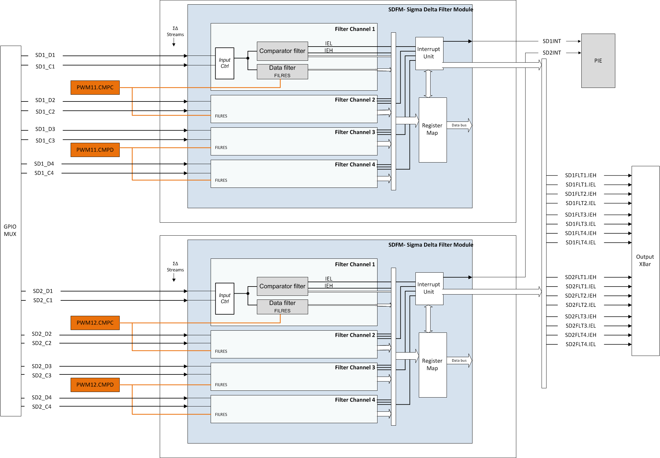
The SDFM is a four-channel digital filter designed specifically for current measurement and resolver position decoding in motor control applications. Each channel can receive an independent sigma-delta (ΣΔ) modulated bit stream. The bit streams are processed by four individually programmable digital decimation filters. The filter set includes a fast comparator for immediate digital threshold comparisons for overcurrent and undercurrent monitoring. Figure 6-56 shows a block diagram of the SDFMs.
SDFM features include:
- Eight external pins per SDFM module:
- Four sigma-delta data input pins per SDFM module (SDx_Dy, where x = 1 to 2 and y = 1 to 4)
- Four sigma-delta clock input pins per SDFM module (SDx_Cy, where x = 1 to 2 and y = 1 to 4)
- Four different configurable modulator clock modes:
- Modulator clock rate equals modulator data rate
- Modulator clock rate running at half the modulator data rate
- Modulator data is Manchester encoded. Modulator clock not required.
- Modulator clock rate is double that of modulator data rate
- Four independent configurable comparator units:
- Four different filter type selection (Sinc1/Sinc2/Sincfast/Sinc3) options available
- Ability to detect over-value and under-value conditions
- Comparator Over-Sampling Ratio (COSR) value for comparator programmable from 1 to 32
- Four independent configurable data filter units:
- Four different filter type selection (Sinc1/Sinc2/Sincfast/Sinc3) options available
- Data filter Over-Sampling Ratio (DOSR) value for data filter unit programmable from 1 to 256
- Ability to enable or disable individual filter module
- Ability to synchronize all four independent filters of a SDFM module using the Master Filter Enable (MFE) bit or the PWM signals.
- Filter data can be 16-bit or 32-bit representation
- PWMs can be used to generate modulator clock for sigma-delta modulators
 Figure 6-56 SDFM Block Diagram