SPNS254A June 2022 – March 2024 TMS570LC4357-SEP
PRODUCTION DATA
- 1
- 1 Features
- 2 Applications
- 3 Description
- 4 Device Comparison
-
5 Terminal Configuration and Functions
- 5.1 GWT BGA Package Ball-Map (337 Terminal Grid Array)
- 5.2
Terminal Functions
- 5.2.1
GWT Package
- 5.2.1.1 Multibuffered Analog-to-Digital Converters (MibADC)
- 5.2.1.2 Enhanced High-End Timer Modules (N2HET)
- 5.2.1.3 RAM Trace Port (RTP)
- 5.2.1.4 Enhanced Capture Modules (eCAP)
- 5.2.1.5 Enhanced Quadrature Encoder Pulse Modules (eQEP)
- 5.2.1.6 Enhanced Pulse-Width Modulator Modules (ePWM)
- 5.2.1.7 Data Modification Module (DMM)
- 5.2.1.8 General-Purpose Input / Output (GIO)
- 5.2.1.9 FlexRay Interface Controller (FlexRay)
- 5.2.1.10 Controller Area Network Controllers (DCAN)
- 5.2.1.11 Local Interconnect Network Interface Module (LIN)
- 5.2.1.12 Standard Serial Communication Interface (SCI)
- 5.2.1.13 Inter-Integrated Circuit Interface Module (I2C)
- 5.2.1.14 Multibuffered Serial Peripheral Interface Modules (MibSPI)
- 5.2.1.15 Ethernet Controller
- 5.2.1.16 External Memory Interface (EMIF)
- 5.2.1.17 Embedded Trace Macrocell Interface for Cortex-R5F (ETM-R5)
- 5.2.1.18 System Module Interface
- 5.2.1.19 Clock Inputs and Outputs
- 5.2.1.20 Test and Debug Modules Interface
- 5.2.1.21 Flash Supply and Test Pads
- 5.2.1.22 Supply for Core Logic: 1.2-V Nominal
- 5.2.1.23 Supply for I/O Cells: 3.3-V Nominal
- 5.2.1.24 Ground Reference for All Supplies Except VCCAD
- 5.2.1.25 Other Supplies
- 5.2.2 Multiplexing
- 5.2.1
GWT Package
-
6 Specifications
- 6.1 Absolute Maximum Ratings
- 6.2 ESD Ratings
- 6.3 Power-On Hours (POH)
- 6.4 Recommended Operating Conditions
- 6.5 Switching Characteristics Over Recommended Operating Conditions for Clock Domains
- 6.6 Wait States Required - L2 Memories
- 6.7 Power Consumption Summary
- 6.8 Input/Output Electrical Characteristics Over Recommended Operating Conditions
- 6.9 Thermal Resistance Characteristics for the BGA Package (GWT)
- 6.10 Timing and Switching Characteristics
-
7 System Information and Electrical Specifications
- 7.1 Device Power Domains
- 7.2 Voltage Monitor Characteristics
- 7.3 Power Sequencing and Power-On Reset
- 7.4 Warm Reset (nRST)
- 7.5 Arm Cortex-R5F CPU Information
- 7.6 Clocks
- 7.7 Clock Monitoring
- 7.8 Glitch Filters
- 7.9 Device Memory Map
- 7.10 Flash Memory
- 7.11 L2RAMW (Level 2 RAM Interface Module)
- 7.12 ECC / Parity Protection for Accesses to Peripheral RAMs
- 7.13 On-Chip SRAM Initialization and Testing
- 7.14 External Memory Interface (EMIF)
- 7.15 Vectored Interrupt Manager
- 7.16 ECC Error Event Monitoring and Profiling
- 7.17 DMA Controller
- 7.18 Real-Time Interrupt Module
- 7.19 Error Signaling Module
- 7.20 Reset / Abort / Error Sources
- 7.21 Digital Windowed Watchdog
- 7.22
Debug Subsystem
- 7.22.1 Block Diagram
- 7.22.2 Debug Components Memory Map
- 7.22.3 Embedded Cross Trigger
- 7.22.4 JTAG Identification Code
- 7.22.5 Debug ROM
- 7.22.6 JTAG Scan Interface Timings
- 7.22.7 Advanced JTAG Security Module
- 7.22.8 Embedded Trace Macrocell (ETM-R5)
- 7.22.9 RAM Trace Port (RTP)
- 7.22.10 Data Modification Module (DMM)
- 7.22.11 Boundary Scan Chain
-
8 Peripheral Information and Electrical Specifications
- 8.1
Enhanced Translator PWM Modules (ePWM)
- 8.1.1 ePWM Clocking and Reset
- 8.1.2 Synchronization of ePWMx Time-Base Counters
- 8.1.3 Synchronizing all ePWM Modules to the N2HET1 Module Time Base
- 8.1.4 Phase-Locking the Time-Base Clocks of Multiple ePWM Modules
- 8.1.5 ePWM Synchronization with External Devices
- 8.1.6 ePWM Trip Zones
- 8.1.7 Triggering of ADC Start of Conversion Using ePWMx SOCA and SOCB Outputs
- 8.1.8 Enhanced Translator-Pulse Width Modulator (ePWMx) Electrical Data/Timing
- 8.2 Enhanced Capture Modules (eCAP)
- 8.3 Enhanced Quadrature Encoder (eQEP)
- 8.4 12-bit Multibuffered Analog-to-Digital Converter (MibADC)
- 8.5 General-Purpose Input/Output
- 8.6 Enhanced High-End Timer (N2HET)
- 8.7 FlexRay Interface
- 8.8 Controller Area Network (DCAN)
- 8.9 Local Interconnect Network Interface (LIN)
- 8.10 Serial Communication Interface (SCI)
- 8.11 Inter-Integrated Circuit (I2C)
- 8.12 Multibuffered / Standard Serial Peripheral Interface
- 8.13 Ethernet Media Access Controller
- 8.1
Enhanced Translator PWM Modules (ePWM)
- 9 Applications, Implementation, and Layout
- 10Device and Documentation Support
- 11Revision History
- 12Mechanical, Packaging, and Orderable Information
Package Options
Refer to the PDF data sheet for device specific package drawings
Mechanical Data (Package|Pins)
- GWT|337
Thermal pad, mechanical data (Package|Pins)
Orderable Information
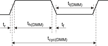
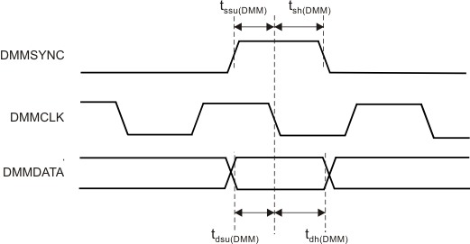
7.22.10.2 Timing Specifications
| PARAMETER | MIN | MAX | UNIT | |
|---|---|---|---|---|
| tcyc(DMM) | Cycle time, DMMCLK clock period | 9.09 | ns | |
| th(DMM) | High-pulse width | ((tcyc(DMM))/2) - ((tr+tf)/2) | ns | |
| tl(DMM) | Low-pulse width | ((tcyc(DMM))/2) - ((tr+tf)/2) | ns | |
 Figure 7-35 DMMCLK Timing
| PARAMETER | MIN | MAX | UNIT | |
|---|---|---|---|---|
| tssu(DMM) | Setup time, SYNC active before clk falling edge | 2 | ns | |
| tsh(DMM) | Hold time, clk falling edge after SYNC deactive | 3 | ns | |
| tdsu(DMM) | Setup time, DATA before clk falling edge | 2 | ns | |
| tdh(DMM) | Hold time, clk falling edge after DATA hold time | 3 | ns | |
 Figure 7-36 DMMDATA Timing
Figure 7-37 shows a case with 1 DMM packet per 2 DMMCLK cycles (Mode = Direct Data Mode, data width = 8, portwidth = 4) where none of the packets received by the DMM are sent out, leading to filling up of the internal buffers. The DMMnENA signal is shown asserted, after the first two packets have been received and synchronized to the HCLK domain. Here, the DMM has the capacity to accept packets D4x, D5x, D6x, D7x. Packet D8 would result in an overflow. Once DMMnENA is asserted, the DMM expects to stop receiving packets after 4 HCLK cycles; once DMMnENA is deasserted, the DMM can handle packets immediately (after 0 HCLK cycles).
 Figure 7-37 DMMnENA Timing