SLIS144B September 2011 – February 2017
PRODUCTION DATA.
- 1 Features
- 2 Applications
- 3 Description
- 4 Revision History
- 5 Device Comparison Table
- 6 Pin Configuration and Functions
- 7 Specifications
- 8 Parameter Measurement Information
- 9 Detailed Description
- 10Application and Implementation
- 11Power Supply Recommendations
- 12Layout
- 13Device and Documentation Support
- 14Mechanical, Packaging, and Orderable Information
Package Options
Mechanical Data (Package|Pins)
- DCK|6
Thermal pad, mechanical data (Package|Pins)
Orderable Information
12 Layout
12.1 Layout Guidelines
To ensure reliability of the device, follow common printed-circuit board (PCB) layout guidelines:
- Leads to the input must be as direct as possible with a minimum conductor length.
- The ground path must have low resistance and low inductance.
- Use short trace-lengths to avoid excessive loading.
- It is common to have a dedicated ground plane on an inner layer of the board.
- Terminals that are connected to ground must have a low-impedance path to the ground plane in the form of wide polygon pours and multiple vias.
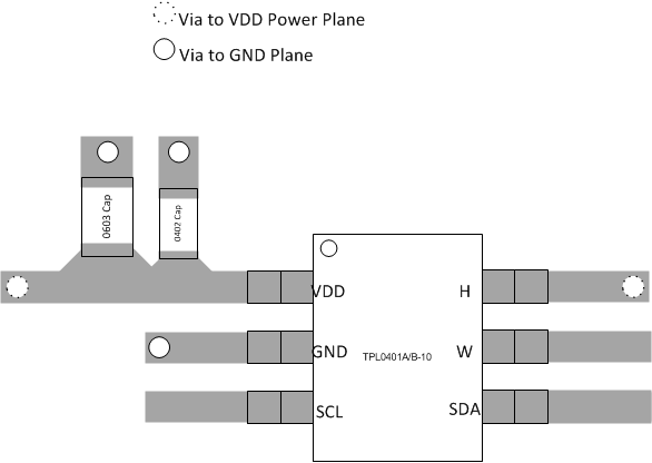
- Use bypass capacitors on power supplies and placed them as close as possible to the VDD pin.
- Apply low equivalent series resistance (0.1-μF to 10-μF tantalum or electrolytic capacitors) at the supplies to minimize transient disturbances and to filter low-frequency ripple.
- To reduce the total I2C bus capacitance added by PCB parasitics, data lines (SCL and SDA) must be as short as possible and the widths of the traces must also be minimized (for example, 5 to 10 mils depending on copper weight).
12.2 Layout Example
 Figure 24. Layout Recommendation