SLVSCE9D June 2014 – October 2017 TPS25942A , TPS25942L , TPS25944A , TPS25944L
UNLESS OTHERWISE NOTED, this document contains PRODUCTION DATA.
- 1 Features
- 2 Applications
- 3 Description
- 4 Revision History
- 5 Device Comparison Table
- 6 Pin Configuration and Functions
- 7 Specifications
- 8 Parameter Measurement Information
-
9 Detailed Description
- 9.1 Overview
- 9.2 Functional Block Diagram
- 9.3
Feature Description
- 9.3.1 Enable and Adjusting Undervoltage Lockout
- 9.3.2 Overvoltage Protection (OVP)
- 9.3.3 Hot Plug-In and In-Rush Current Control
- 9.3.4 Overload and Short Circuit Protection
- 9.3.5 Reverse Current Protection
- 9.3.6 FAULT Response
- 9.3.7 Current Monitoring
- 9.3.8 Power Good Comparator
- 9.3.9 IN, OUT and GND Pins
- 9.3.10 Thermal Shutdown
- 9.4 Device Functional Modes
-
10Application and Implementation
- 10.1 Application Information
- 10.2
Typical Application
- 10.2.1 Design Requirements
- 10.2.2
Detailed Design Procedure
- 10.2.2.1 Step by Step Design Procedure
- 10.2.2.2 Programming the Current-Limit Threshold: R(ILIM) Selection
- 10.2.2.3 Undervoltage Lockout and Overvoltage Set Point
- 10.2.2.4 Programming Current Monitoring Resistor—RIMON
- 10.2.2.5 Setting Output Voltage Ramp Time (tdVdT)
- 10.2.2.6 Programing the Power Good Set Point
- 10.2.2.7 Support Component Selections—R6, R7 and CIN
- 10.2.3 Application Curves
- 10.3 System Examples
- 11Power Supply Recommendations
- 12Layout
- 13Device and Documentation Support
- 14Mechanical, Packaging, and Orderable Information
Package Options
Mechanical Data (Package|Pins)
- RVC|20
Thermal pad, mechanical data (Package|Pins)
- RVC|20
Orderable Information
10.3.1 Active ORing (Auto-Power Multiplexer) Operation
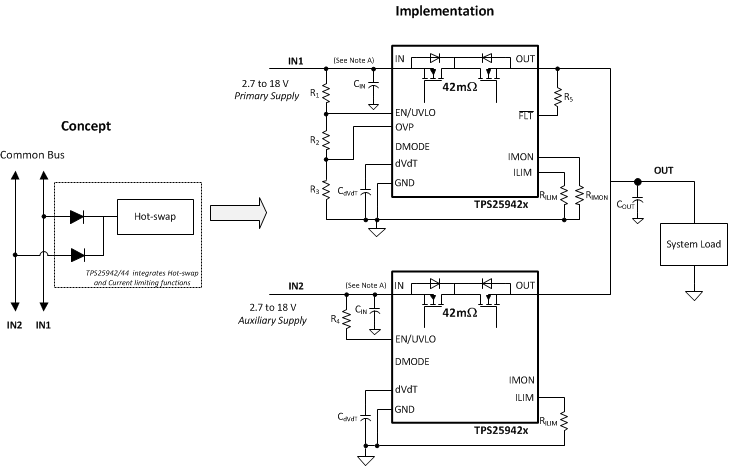
A typical redundant power supply configuration of the system is shown in Figure 74. Schottky ORing diodes have been popular for connecting parallel power supplies, such as parallel operation of wall adapter with a battery or a hold-up storage capacitor. The disadvantage of using ORing diodes is high voltage drop and associated power loss. The TPS25942 and TPS25944 with an integrated, low-ohmic N-channel FET provide a simple and efficient solution. Figure 74 shows the Active ORing implementation using the devices.

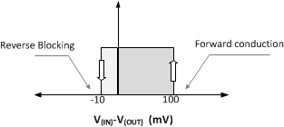
A fast reverse comparator controls the internal FET and it is turned ON or OFF with hysteresis as shown in Figure 75. The internal FET is turned ON in less than 4 us (typical) when the forward voltage drop V(IN) – V(OUT) exceeds 100 mV and is turned off in 1 µs (typical) as soon as V(IN) – V(OUT) falls below –10 mV. When internal FET is turned ON, the ORed input supply experiences momentary in-rush current drawn as the FET turns on charging the bus capacitance. In addition, device can be operated in Diode Mode by independently controlling DMODE pin.
 Figure 75. Active ORing Thresholds
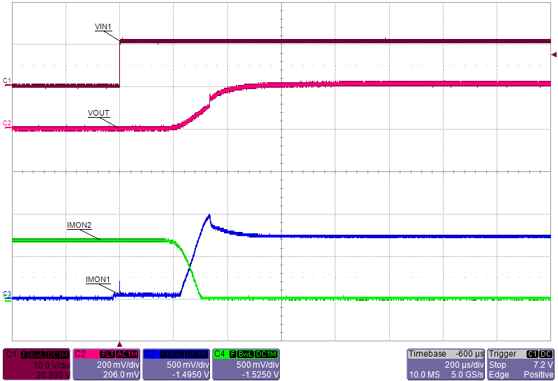
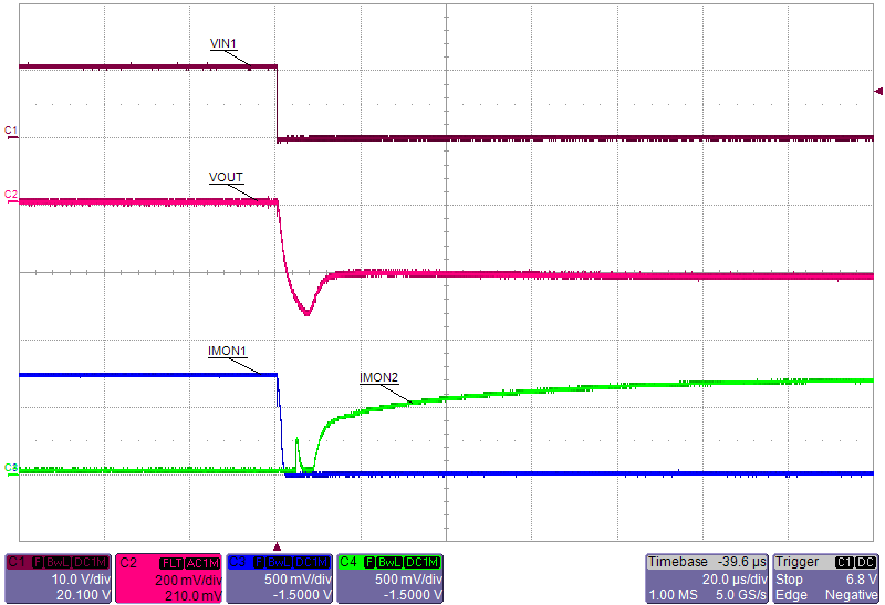
Figure 75 shows typical switch-over waveforms of Active ORing implementation using the TPS25942 or TPS25944.

| V(IN1) = 12.2 V | V(IN2) = 12 V | C(OUT) = 100 µF |
| RL = 14 Ω | C(dVdT) = 1.5 nF |

| V(IN1) = 12.2 V | V(IN2) = 12 V | C(OUT) = 100 µF |
| RL = 14 Ω | C(dVdT) = 1.5 nF |
When bus voltages (IN1 and IN2) are matched, device in each rail sees a forward voltage drop and is ON delivering the load current. During this period, current is shared between the rails in the ratio of differential voltage drop across each device.
In addition to above, the devices provide inrush current limit and protects each rail from potential overload and short circuit faults.