-
TPS3808Gxx-Q1 Low-Quiescent-Current Programmable-Delay Supervisory Circuit
- 1 Features
- 2 Applications
- 3 Description
- 4 Revision History
- 5 Device Comparison Table
- 6 Pin Configuration and Functions
- 7 Specifications
- 8 Detailed Description
- 9 Applications and Implementation
- 10Power Supply Recommendations
- 11Layout
- 12Device and Documentation Support
- 13Mechanical, Packaging, and Orderable Information
- IMPORTANT NOTICE
Package Options
Mechanical Data (Package|Pins)
Thermal pad, mechanical data (Package|Pins)
- DRV|6
Orderable Information
TPS3808Gxx-Q1 Low-Quiescent-Current Programmable-Delay Supervisory Circuit
1 Features
- Qualified for Automotive Applications
- Power-On Reset Generator With Adjustable Delay Time: 1.25 ms to 10 s
- Very Low Quiescent Current: 2.4 μA Typical
- High Threshold Accuracy: 0.5% Typical
- Fixed Threshold Voltages for Standard Voltage Rails From 1.2 V to 5 V and Adjustable Voltage Down to 0.4 V Are Available
- Manual Reset (MR) Input
- Open-Drain RESET Output
- Temperature Range: –40°C to +125°C
- Small SOT-23 Package and WSON Package (TPS3808G01QDRVRQ1 only)
2 Applications
- DSP or Microcontroller Applications
- FPGA and ASIC Applications
- Automotive Vision
- Automotive Radar
3 Description
The TPS3808Gxx-Q1 microprocessor supervisory circuits monitor system voltages from 0.4 V to 5 V, asserting an open-drain RESET signal when the SENSE voltage drops below a preset threshold or when the manual reset (MR) pin drops to a logic low. The RESET output remains low for the user-adjustable delay time after the SENSE voltage and MR return above their thresholds.
The TPS3808Gxx-Q1 device uses a precision reference to achieve 0.5% threshold accuracy for VIT ≤ 3.3 V. The reset delay time can be set to 20 ms by disconnecting the CT pin, 300 ms by connecting the CT pin to VDD using a resistor, or can be user-adjusted from 1.25 ms to 10 s by connecting the CT pin to an external capacitor. The TPS3808Gxx-Q1 has a very low typical quiescent current of 2.4 μA, so it is well suited for battery-powered applications. The device is available in a small SOT-23 package (one option available in WSON) and is fully specified over a temperature range of –40°C to +125°C (TJ).
For more information about TI's voltage supervisor portfolio, visit the Supervisor and Reset IC Overview Page page.
Device Information(1)
| PART NUMBER | PACKAGE | BODY SIZE (NOM) |
|---|---|---|
| TPS3808Gxx-Q1 | SOT-23 (6) | 2.90 mm × 1.60 mm |
| WSON (6) | 2.00 mm × 2.00 mm |
- For all available packages, see the orderable addendum at the end of the data sheet.
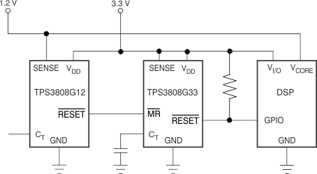
Typical Application Schematic

4 Revision History
Changes from I Revision (June 2015) to J Revision
- Added column for WSON pins Go
- Changed unit for last row of td row in Timing Requirements from "ms" to "s" and "TYP" to "NOM" in middle unit columnGo
Changes from H Revision (June 2012) to I Revision
- Added ESD Ratings table, Feature Description section, Device Functional Modes, Application and Implementation section, Power Supply Recommendations section, Layout section, Device and Documentation Support section, and Mechanical, Packaging, and Orderable Information section Go
Changes from G Revision (November, 2010) to H Revision
- Changed ISENSE from µA to nAGo
5 Device Comparison Table
| ORDERABLE PART NUMBER | NOMINAL SUPPLY VOLTAGE | THRESHOLD VOLTAGE (VIT) |
|---|---|---|
| TPS3808G01QDRVRQ1 | Adjustable | 0.405 V |
| TPS3808G01QDBVRQ1 | ||
| TPS3808G12QDBVRQ1 | 1.2 V | 1.12 V |
| TPS3808G125QDBVRQ1 | 1.25 V | 1.16 V |
| TPS3808G15QDBVRQ1 | 1.5 V | 1.4 V |
| TPS3808G18QDBVRQ1 | 1.8 V | 1.67 V |
| TPS3808G30QDBVRQ1 | 3 V | 2.79 V |
| TPS3808G33QDBVRQ1 | 3.3 V | 3.07 V |
| TPS3808G50QDBVRQ1 | 5 V | 4.65 V |
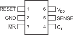
6 Pin Configuration and Functions


Pin Functions
| PIN | I/O | DESCRIPTION | ||
|---|---|---|---|---|
| NAME | SOT-23 | WSON | ||
| CT | 4 | 3 | I | Reset period programming pin. Connecting this pin to VDD through a 40-kΩ to 200-kΩ resistor or leaving it open results in fixed delay times (see Electrical Characteristics). Connecting this pin to a ground referenced capacitor ≥ 100 pF gives user-programmable delay time. See the Selecting the Reset Delay Time for more information. |
| GND | 2 | 5 | — | Ground |
| MR | 3 | 4 | I | Manual reset. Driving this pin low asserts RESET. MR is internally tied to VDD by a 90-kΩ pullup resistor. |
| RESET | 1 | 6 | O | Reset. This is an open-drain output that is driven to a low impedance state when RESET is asserted (either the SENSE input is lower than the threshold voltage (VIT) or the MR pin is set to a logic low). RESET remains low (asserted) for the reset period after both SENSE is above VIT and MR is set to a logic high. A pullup resistor from 10 kΩ to 1 MΩ must be used on this pin and allows the reset pin to attain voltages higher than VDD. |
| SENSE | 5 | 2 | I | Voltage sense. This pin is connected to the voltage to be monitored. If the voltage at this terminal drops below the threshold voltage (VIT), RESET is asserted. |
| VDD | 6 | 1 | I | Supply voltage. It is good analog design practice to place a 0.1-μF ceramic capacitor close to this pin. |
| Thermal Pad | — | Pad | — | Thermal pad; connect to ground plan to enhance thermal performance of the package. |