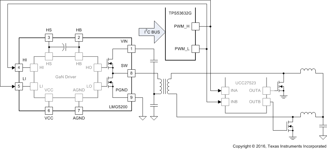
The TPS53632G device is a half-bridge PWM controller with D-CAP+™ architecture that provides fast transient response, lowest output capacitance and high efficiency in single stage conversion directly from 48-V bus. The TPS53632G device supports the standard I2C Rev 3.0 interface for dynamic control of the output voltage and current monitor telemetry. Paired with TI GaN power stages and drivers, the TPS53632G can switch up to 1 MHz to minimize magnetic component size and reduce overall board space. The LMG5200 GaN power stage is designed specifically for this controller to achieve high frequency and efficiency as high as 92% with 48-V to 1-V conversion.
Other features include adjustable control of output slew rate and voltage positioning. In addition, the TPS53632G device can be used along with other TI discrete power MOSFETs and drivers for silicon-based half bridge solutions. The TPS53632G device is packaged in a space saving, thermally enhanced, 32-pin VQFN package and is rated to operate at a range between –10°C and 105°C.
PART NUMBER | PACKAGE | BODY SIZE |
---|---|---|
TPS53632G | VQFN | 4 mm × 4 mm |
WHITESPACE
WHITESPACE
Changes from * Revision (April 2016) to A Revision
PIN | I/O | DESCRIPTION | |
---|---|---|---|
NAME | NO. | ||
COMP | 26 | I | Error amplifier summing node. Resistors between the VREF pin and the COMP pin (RCOMP) and between the COMP pin and the DROOP pin (RDROOP) set the droop gain. |
CSP1 | 17 | I | Positive current sense inputs. Connect to the most positive node of current sense resistor or inductor DCR sense network. Tie CSP2 or CSP1 (in that order) to a 3.3-V supply to disable the phase. |
CSP2 | 20 | ||
PU3 | 21 | Connect to 3.3-V supply. | |
CSN1 | 18 | I | Negative current sense inputs. Connect to the most negative node of current sense resistor or inductor DCR sense network. CSN1 has a secondary OVP comparator and includes the soft-stop, pull-down transistor. |
CSN2 | 19 | ||
NC | 22 | – | No connect. |
DROOP | 25 | O | Error amplifier output. A resistor pair between this pin and the VREF pin and between the COMP pin and this pin sets the droop gain. ADROOP = 1 + RDROOP / RCOMP. |
EN | 8 | I | Enable. 100-ns de-bounce. Regulator enters low-power mode, but retains start-up settings when brought low. |
FREQ-P | 10 | I | A resistor between this pin and GND sets the per-phase switching frequency. Add a resistor to VREF to disable dynamic phase add and drop operation. |
GFB | 23 | I | Voltage sense return. Tie to GND on PCB with a 10-Ω resistor to provide feedback when the microprocessor is not populated. |
GND | 29 | – | Analog circuit reference. Tie this pin to a quiet point on the ground plane. |
IMON | 13 | O | Analog current monitor output. VIMON = ΣVISENSE × (1 + RIMON/ROCP). |
OCP-I | 12 | I/O | Voltage divider to IMON. Resistor ratio sets the IMON gain (see IMON pin). A resistor between this pin and GND (ROCP) selects 1 of 8 OCP levels (per phase, latched at start-up). |
PU | 9 | I | Pull-up to VREF through 10-kΩ resistor. |
PGOOD | 3 | O | Power good output. Open-drain. |
PWM-HI | 6 | O | PWM controls for the external driver; 5-V logic level. Controller forces signal to the tri-state level when needed. |
PWM-LO | 5 | ||
NC | 4 | – | No connect. |
NC | 30 | – | No connect. |
32 | |||
RAMP | 11 | I | Voltage divider to VREF. A resistor to GND sets the ramp setting voltage. The RAMP setting can be used to override the factory ramp setting. |
SCL | 31 | I | Serial digital clock line. |
SDA | 1 | I/O | Serial digital I/O line. |
SKIP | 7 | O | When high, the driver enters FCCM mode; otherwise, the driver is in DCM mode. Driving the tri-state level on this pin puts the drivers into a low power sleep mode. |
SLEWA | 15 | I | The voltage sets the 3 LSBs of the I2C address. The resistance to GND selects 1 of 8 slew rates. The start-up slew rate (EN transitions high) is SLEWRATE/2. The ADDRESS and SLEWRATE values are latched at start-up. |
VINTF | 14 | I | Input voltage to interface logic. Voltage level can be between 1.62 V and 3.5 V. |
V5A | 28 | I | 5-V power input for analog circuits; connect through resistor to 5-V plane and bypass to GND with ceramic capacitor with a value of at least 1 µF. |
VBUS | 16 | I | The VBUS pin provides input voltage information to the on-time circuits for both converters. |
VDD | 2 | I | 3.3-V digital power input. Bypass this pin to GND with a capacitor with a value of at least 1 µF. |
VFB | 24 | I | Voltage sense line. Tie directly to VOUT sense point of processor. Tie to VOUT on PCB with a 10-Ω resistor to provide feedback when the microprocessor is not populated. The resistance between VFB and GFB is > 1 MΩ |
VREF | 27 | O | 1.7-V, 500-µA reference. Bypass to GND with a 0.22-µF ceramic capacitor. |
PAD | GND | – | Thermal pad Tie to the ground plane with multiple vias. |
MIN | MAX | UNIT | ||
---|---|---|---|---|
Input voltage | V5A | –0.3 | 6.0 | V |
VBUS | –0.3 | 30.0 | ||
VDD | –0.3 | 3.6 | ||
COMP, CSP1, CSP2, CSN1, CSN2, DROOP, EN, FREQ-P, IMON, OCP-I, O-USR, RAMP, SCL, SDA, SLEWA, VFB, VINTF, VREF | –0.3 | 3.6 | ||
GFB | –0.2 | 0.2 | ||
Output voltage | PGOOD | –0.3 | 3.6 | V |
PWM-LO, PWM-HI, SKIP | –0.3 | 6.0 | ||
Operating junction temperature, TJ | –40 | 150 | °C | |
Storage temperature, Tstg | 150 | °C |
VALUE | UNIT | |||
---|---|---|---|---|
V(ESD) | Electrostatic discharge | Human body model (HBM) ESD stress voltage(1) | ±2000 | V |
Charged device model (CDM) ESD stress voltage(2) | ±750 | V |
MIN | MAX | UNIT | |||
---|---|---|---|---|---|
VI | Input voltage | V5A | 4.5 | 5.5 | V |
VBUS | –0.1 | 28 | |||
VDD | 3.1 | 3.5 | |||
CSN1, CSN2, CSP1, CSP2, IMON, OCP-I, O-USR, RAMP, SCL, SDA, VFB, VINTF, VREF | –0.1 | 3.5 | |||
COMP, DROOP, EN, FREQ-P, SLEWA | –0.1 | 5.5 | |||
GFB | –0.1 | 0.1 | |||
VO | Output voltage | PGOOD | –0.1 | 3.5 | V |
PWM-LO, PWM-HI, SKIP | –0.1 | 5.5 | |||
TA | Operating ambient temperature | –10 | 105 | °C |
THERMAL METRIC(1) | TPS53632G | UNITS | |
---|---|---|---|
RSM (VQFN) | |||
32 PINS | |||
RθJA | Junction-to-ambient thermal resistance | 37.2 | °C/W |
RθJCtop | Junction-to-case (top) thermal resistance | 31.9 | °C/W |
RθJB | Junction-to-board thermal resistance | 8.1 | °C/W |
RψJT | Junction-to-top characterization parameter | 0.4 | °C/W |
RψJB | Junction-to-board characterization parameter | 7.9 | °C/W |
RθJCbot | Junction-to-case (bottom) thermal resistance | 2.2 | °C/W |
PARAMETER | CONDITIONS | MIN | TYP | MAX | UNIT | |
---|---|---|---|---|---|---|
POWER SUPPLY: CURRENTS, UVLO AND POWER-ON-RESET | ||||||
IV5-3P | V5A supply current | VDAC < VVFB < (VDAC + 100 mV), EN = ‘HI’ | 3.6 | 6.0 | mA | |
IVDD-3P | VDD supply current | VDAC < VVFB < (VDAC + 100 mV), EN = ‘HI’, digital buses idle | 0.2 | 0.8 | ||
IV5STBY | V5A standby current | EN = ‘LO’ | 125 | 200 | µA | |
IVDDSTBY | VDD standby current | EN = ‘LO’ | 23 | 40 | ||
IVDD-1P8 | VINTF supply current | All conditions, digital buses idle | 1.7 | 5.0 | ||
VUVLOH | V5A UVLO ‘OK’ threshold | VVFB < 200 mV, Ramp up, VVDD > 3 V, EN = ’HI’, switching begins. | 4.2 | 4.4 | 4.52 | V |
VUVLOL | V5A UVLO fault threshold | Ramp down, EN = ’HI’, VVDD > 3 V, VVFB = 100 mV, restart if 5-V falls below VPOR then rises > VUVLOH, or EN is toggled w/ VV5A > VUVLOH | 4.00 | 4.2 | 4.35 | |
VPOR | V5A fault latch reset threshold | Ramp down, EN = ‘HI’, VVDD > 3 V. Can restart if 5-V rises to VUVLOH and no other faults present. | 1.2 | 1.9 | 2.5 | |
V3UVLOH | VDD UVLO ‘OK’ threshold | VVFB < 200 mV. Ramp up, VV5A > 4.5 V, EN = ’HI’, Switching begins. | 2.5 | 2.8 | 3.0 | |
V3UVLOL | Fault threshold | Ramp down, EN = ’HI’, V5A > 4.5V, VFB = 100 mV, restart if 5-V dips below VPOR then rises > VUVLOH or EN is toggled with 5 V > VUVLOH | 2.4 | 2.6 | 2.8 | |
VPOR | VDD fault latch | Ramp down, EN = ‘HI’, VV5A > 4.5 V, can restart if 5-V supply rises to VUVLOH and no other faults present. | 1.2 | 1.9 | 2.5 | |
VINTFUVLOH | VINTF UVLO OK | Ramp up, EN = ’HI’, VV5A > 4.5 V, VVFB = 100 mV | 1.4 | 1.5 | 1.6 | |
VINTFUVLOL | VINTF UVLO falling | Ramp down, EN = ’HI’, VV5A > 4.5 V, VVFB = 100 mV | 1.3 | 1.4 | 1.5 | |
REFERENCES: DAC, VREF, VFB DISCHARGE | ||||||
VVIDSTP | VID step size | Change VID0 HI to LO to HI | 10 | mV | ||
VDAC1 | VFB tolerance | No load active, 1.36 V ≤ VVFB ≤ 1.52 V, IOUT = 0 A | –9 | 9 | ||
VDAC2 | VFB tolerance | No load medium, 1.0 V ≤ VVFB ≤ 1.35 V, IOUT = 0 A | –8 | 8 | ||
No load medium, 0.5 V ≤ VVFB ≤ 0.99 V, IOUT = 0 A | -7 | 7 | ||||
VVREF | VREF output | VREF output 4.5 V ≤ VV5A ≤ 5.5 V, IVREF = 0 A | 1.66 | 1.700 | 1.74 | V |
VVREFSRC | VREF output source | 0 A ≤ IREF ≤ 500 µA, HP-2 | –4 | -3 | mV | |
VVREFSNK | VREF output sink | –500 A ≤ IREF ≤ 0 A, HP-2 | 3 | 4 | ||
VVBOOT | Internal VFB initial boot voltage | Initial DAC boot voltage | 0.99 | 1.00 | 1.01 | V |
RAMP SETTINGS | ||||||
VRAMP | Compensation ramp | RRAMP = 30 kΩ | 60 | mV | ||
RRAMP = 56 kΩ | 120 | |||||
RRAMP = 100 kΩ | 160 | |||||
RRAMP ≥ 150 kΩ | 40 | |||||
VOLTAGE SENSE: VFB AND GFB | ||||||
RVFB | VFB/GFB Input resistance | Not in fault, disable or UVLO, VVFB = VDAC = 1.5 V, VGFB = 0 V, measure from VFB to GFB |
1 | MΩ | ||
VDELGND | GFB Differential | GND to GFB | ±100 | mV | ||
CURRENT MONITOR | ||||||
VALADC | IMON ADC output | ∑∆CS = 0 mV, AIMON = 3.867 | 00h | |||
∑∆CS = 1.5 mV, AIMON = 3.867 | 19h | |||||
∑∆CS = 7.5 mV, AIMON = 3.867 | 80h | |||||
∑∆CS = 15 mV, AIMON = 3.867 | FFh | |||||
LRIMON | IMON linear range | Each phase, CSPx – CSNx | 50 | mV | ||
CURRENT SENSE: OVER CURRENT PROTECTION, PHASE ADD AND DROP, AND PHASE BALANCE | ||||||
VOCPP | OCP voltage (valley current limit) | ROCP-I = 20 kΩ | 3.7 | 7.6 | 11.4 | mV |
ROCP-I = 24 kΩ | 6.6 | 10.5 | 14.1 | |||
ROCP-I = 30 kΩ | 10.6 | 14.5 | 18.0 | |||
ROCP-I = 39 kΩ | 15.4 | 19.5 | 23.0 | |||
ROCP-I = 56 kΩ | 21.3 | 25.4 | 29.0 | |||
ROCP-I = 75 kΩ | 28.4 | 32.5 | 36.2 | |||
ROCP-I = 100 kΩ | 36.3 | 40.5 | 44.0 | |||
ROCP-I = 150 kΩ | 45.0 | 49.3 | 53.0 | |||
ICS | CS pin input bias current | CSPx and CSNx | –500 | 0.2 | 500 | nA |
AV-EA | Error amplifier total voltage gain(1) | VFB to DROOP | 80 | dB | ||
IEA_SR | Error amplifier source current | IDROOP, VVFB = VDAC + 50 mV, RCOMP = 1 kΩ | 1 | mA | ||
IEA_SK | Error amplifier sink current | IDROOP, VVFB = VDAC – 50mV, RCOMP = 1 kΩ | –1 | |||
ACSINT | Internal current sense gain | Gain from CSPx – CSNx to PWM comparator, RSKIP = Open | 5.8 | 6.0 | 6.2 | V/V |
RSFTSTP | Soft-stop transistor resistance | Connected to CSN1 | 100 | 200 | Ω | |
RVIN | VIN resistance | EN = HI | 350 | 600 | kΩ | |
EN = LOW or STBY | 10 | MΩ | ||||
PROTECTION: OVP, UVP, PGOOD AND THERMAL SHUTDOWN | ||||||
VOVPH | Fixed OVP voltage | VCSN1 > VOVPH for 1 µs | 1.60 | 1.70 | 1.80 | V |
VPGDH | PGOOD high threshold | Measured at the VFB pin w/r/t VID code, device latches OFF | 190 | 245 | mV | |
VPGDL | PGOOD low threshold | Measured at the VFB pin w/r/t VID code, device latches OFF | -348 | -280 | ||
PWM AND SKIP OUTPUTS: I/O VOLTAGE AND CURRENT | ||||||
VP-S_L | PWMx/SKIP - Low | PWMILOAD = ± 1 mA, SKIPILOAD = ± 100 µA | 0.15 | 0.3 | V | |
VP-S_H | PWMx/SKIP - High | PWMILOAD = ± 1 mA, SKIPILOAD = ± 100 µA | 4.2 | |||
LOGIC INTERFACE: VOLTAGE AND CURRENT | ||||||
RVRTTL | Pull-down resistance | VSDA = 0.31 | 4 | 15 | Ω | |
RVRPG | VPGOOD= 0.31 | 36 | 50 | |||
IVRTTLK | Logic leakage current | VSCL= 1.8 V, VSDA = 1.8 V, VPGOOD = 3.3 V | -2 | 0.2 | 2 | µA |
VIL | Low-level Input voltage | SCL, SDA; VVINTF = 1.8 V | 0.6 | V | ||
VIH | High-level Input voltage | 1.2 | ||||
IENH | I/O leakage, EN | Leakage current , VEN = 1.8 V | 24 | 40 | µA |