SLUSDP0A August 2019 – May 2021 TPS53676
PRODUCTION DATA
- 1 Features
- 2 Applications
- 3 Description
- 4 Revision History
- 5 Pin Configuration and Functions
-
6 Specifications
- 6.1 Absolute Maximum Ratings
- 6.2 Recommended Operating Conditions
- 6.3 ESD Ratings
- 6.4
Electrical Specifications
- 6.4.1 Thermal Information
- 6.4.2 Supply
- 6.4.3 DAC and Voltage Feedback
- 6.4.4 Control Loop Parameters
- 6.4.5 Dynamic VID (DVID) Tuning
- 6.4.6 Undershoot Reduction (USR) and Overshoot Reduciton (OSR)
- 6.4.7 Dynamic Phase Shedding (DPS)
- 6.4.8 Turbo Mode and Thermal Balance Management (TBM)
- 6.4.9 Overcurrent Limit (OCL)
- 6.4.10 Telemetry
- 6.4.11 Phase-Locked Loop and Closed-Loop Frequency Control
- 6.4.12 Logic Interface
- 6.4.13 Current Sensing and Current Sharing
- 6.4.14 Pin Detection Thresholds
- 6.4.15 ADDR Pinstrap Decoding
- 6.4.16 BOOT_CHA Pinstrap Decoding
- 6.4.17 Timing Specifications
- 6.4.18 Faults and Converter Protection
- 6.4.19 PMBus/AVS Interfaces
-
7 Detailed Description
- 7.1 Overview
- 7.2 Functional Block Diagram
- 7.3 Power-up and initialization
- 7.4
Pin connections and bevahior
- 7.4.1 Supplies: VCC and VREF
- 7.4.2 Differential remote sensing and output voltage scaling: AVSP/AVSN, BVSP/BVSN
- 7.4.3 Input current sensing: VIN_CSNIN and CSPIN
- 7.4.4 Pin-strap detection and PIN_DETECT_OVERRIDE
- 7.4.5 Enable and disable: AVR_EN and BVR_EN
- 7.4.6 System feedback: AVR_RDY and BVR_RDY
- 7.4.7 Catastrophic fault alert: VR_FAULT#
- 7.4.8 Output voltage reset: RESET#
- 7.4.9 Synchronization: SYNC
- 7.4.10 Smart power stage connections: PWM, CSP and TSEN
- 7.4.11 PMBus pins: SMB_DIO, SMB_CLK, and SMB_ALERT#
- 7.4.12 AVSBus: AVS_CLK, AVS_MDATA, AVS_SDATA, and AVS_VDDIO
- 7.5 Advanced power management functions
- 7.6
Control Loop Theory of Operation
- 7.6.1 Adaptive voltage positioning and DC load line (droop)
- 7.6.2 DCAP+ conceptual overview
- 7.6.3 Off-time control: loop compensation and transient tuning
- 7.6.4 On-time control: adaptive ton and autobalance current sharing
- 7.6.5 Load transient response
- 7.6.6 Forced minimum on-time, minimum off-time and leading-edge blanking time
- 7.6.7 Nonlinear: undershoot reduction (USR), overshoot reduction (OSR) and dynamic integration
- 7.7
Power supply fault protection
- 7.7.1 Host notification and status reporting
- 7.7.2 Fault type and response definitions
- 7.7.3 Fault behavior summary
- 7.7.4
Detailed fault descriptions
- 7.7.4.1 Overvoltage fault (OVF) and warning (OVW)
- 7.7.4.2 Undervoltage fault (UVF) and warning (UVW)
- 7.7.4.3 Maximum turn-on time exceeded (TON_MAX)
- 7.7.4.4 Output commanded out-of-bounds (VOUT_MIN_MAX)
- 7.7.4.5 Overcurrent fault (OCF), warning (OCW), and per-phase overcurrent limit (OCL)
- 7.7.4.6 Current share warning (ISHARE)
- 7.7.4.7 Overtemperature fault protection (OTF) and warning (OTW)
- 7.7.4.8 Powerstage fault (TAO_HIGH) and powerstage not ready (TAO_LOW)
- 7.7.4.9 Input overvoltage fault (VIN_OVF) and warning (VIN_OVW)
- 7.7.4.10 Input undervoltage fault (VIN_UVF), warning (VIN_UVW) and turn-on voltage (VIN_ON)
- 7.7.4.11 Input overcurrent fault (IIN_OCF) and warning (IIN_OCW)
- 7.7.4.12 Input overpower warning (PIN_OPW)
- 7.7.4.13 PMBus command, memory and logic errors (CML)
- 7.8
Programming
- 7.8.1
PMBus Interface
- 7.8.1.1 PMBus transaction types
- 7.8.1.2 PMBus data formats
- 7.8.1.3 Raw non-volatile memory programming
- 93
- 7.8.1.4
PMBus Command Descriptions
- 7.8.1.4.1 (00h) PAGE
- 7.8.1.4.2 (01h) OPERATION
- 7.8.1.4.3 (02h) ON_OFF_CONFIG
- 7.8.1.4.4 (03h) CLEAR_FAULTS
- 7.8.1.4.5 (04h) PHASE
- 7.8.1.4.6 (05h) PAGE_PLUS_WRITE
- 7.8.1.4.7 (06h) PAGE_PLUS_READ
- 7.8.1.4.8 (10h) WRITE_PROTECT
- 7.8.1.4.9 (15h) STORE_USER_ALL
- 7.8.1.4.10 (16h) RESTORE_USER_ALL
- 7.8.1.4.11 (19h) CAPABILITY
- 7.8.1.4.12 (1Bh) SMBALERT_MASK_WORD
- 7.8.1.4.13 (1Bh) SMBALERT_MASK_VOUT
- 7.8.1.4.14 (1Bh) SMBALERT_MASK_IOUT
- 7.8.1.4.15 (1Bh) SMBALERT_MASK_INPUT
- 7.8.1.4.16 (1Bh) SMBALERT_MASK_TEMPERATURE
- 7.8.1.4.17 (1Bh) SMBALERT_MASK_CML
- 7.8.1.4.18 (1Bh) SMBALERT_MASK_MFR
- 7.8.1.4.19 (20h) VOUT_MODE
- 7.8.1.4.20 (21h) VOUT_COMMAND
- 7.8.1.4.21 (22h) VOUT_TRIM
- 7.8.1.4.22 (24h) VOUT_MAX
- 7.8.1.4.23 (25h) VOUT_MARGIN_HIGH
- 7.8.1.4.24 (26h) VOUT_MARGIN_LOW
- 7.8.1.4.25 (27h) VOUT_TRANSITION_RATE
- 7.8.1.4.26 (28h) VOUT_DROOP
- 7.8.1.4.27 (29h) VOUT_SCALE_LOOP
- 7.8.1.4.28 (2Bh) VOUT_MIN
- 7.8.1.4.29 (33h) FREQUENCY_SWITCH
- 7.8.1.4.30 (34h) POWER_MODE
- 7.8.1.4.31 (35h) VIN_ON
- 7.8.1.4.32 (38h) IOUT_CAL_GAIN
- 7.8.1.4.33 (39h) IOUT_CAL_OFFSET
- 7.8.1.4.34 (40h) VOUT_OV_FAULT_LIMIT
- 7.8.1.4.35 (41h) VOUT_OV_FAULT_RESPONSE
- 7.8.1.4.36 (42h) VOUT_OV_WARN_LIMIT
- 7.8.1.4.37 (43h) VOUT_UV_WARN_LIMIT
- 7.8.1.4.38 (44h) VOUT_UV_FAULT_LIMIT
- 7.8.1.4.39 (45h) VOUT_UV_FAULT_RESPONSE
- 7.8.1.4.40 (46h) IOUT_OC_FAULT_LIMIT
- 7.8.1.4.41 (47h) IOUT_OC_FAULT_RESPONSE
- 7.8.1.4.42 (4Ah) IOUT_OC_WARN_LIMIT
- 7.8.1.4.43 (4Fh) OT_FAULT_LIMIT
- 7.8.1.4.44 (50h) OT_FAULT_RESPONSE
- 7.8.1.4.45 (51h) OT_WARN_LIMIT
- 7.8.1.4.46 (55h) VIN_OV_FAULT_LIMIT
- 7.8.1.4.47 (56h) VIN_OV_FAULT_RESPONSE
- 7.8.1.4.48 (57h) VIN_OV_WARN_LIMIT
- 7.8.1.4.49 (58h) VIN_UV_WARN_LIMIT
- 7.8.1.4.50 (59h) VIN_UV_FAULT_LIMIT
- 7.8.1.4.51 (5Ah) VIN_UV_FAULT_RESPONSE
- 7.8.1.4.52 (5Bh) IIN_OC_FAULT_LIMIT
- 7.8.1.4.53 (5Ch) IIN_OC_FAULT_RESPONSE
- 7.8.1.4.54 (5Dh) IIN_OC_WARN_LIMIT
- 7.8.1.4.55 (60h) TON_DELAY
- 7.8.1.4.56 (61h) TON_RISE
- 7.8.1.4.57 (62h) TON_MAX_FAULT_LIMIT
- 7.8.1.4.58 (63h) TON_MAX_FAULT_RESPONSE
- 7.8.1.4.59 (64h) TOFF_DELAY
- 7.8.1.4.60 (65h) TOFF_FALL
- 7.8.1.4.61 (6Bh) PIN_OP_WARN_LIMIT
- 7.8.1.4.62 (78h) STATUS_BYTE
- 7.8.1.4.63 (79h) STATUS_WORD
- 7.8.1.4.64 (7Ah) STATUS_VOUT
- 7.8.1.4.65 (7Bh) STATUS_IOUT
- 7.8.1.4.66 (7Ch) STATUS_INPUT
- 7.8.1.4.67 (7Dh) STATUS_TEMPERATURE
- 7.8.1.4.68 (7Eh) STATUS_CML
- 7.8.1.4.69 (80h) STATUS_MFR_SPECIFIC
- 7.8.1.4.70 (88h) READ_VIN
- 7.8.1.4.71 (89h) READ_IIN
- 7.8.1.4.72 (8Bh) READ_VOUT
- 7.8.1.4.73 (8Ch) READ_IOUT
- 7.8.1.4.74 (8Dh) READ_TEMPERATURE_1
- 7.8.1.4.75 (96h) READ_POUT
- 7.8.1.4.76 (97h) READ_PIN
- 7.8.1.4.77 (98h) PMBUS_REVISION
- 7.8.1.4.78 (99h) MFR_ID
- 7.8.1.4.79 (9Ah) MFR_MODEL
- 7.8.1.4.80 (9Bh) MFR_REVISION
- 7.8.1.4.81 (9Dh) MFR_DATE
- 7.8.1.4.82 (ADh) IC_DEVICE_ID
- 7.8.1.4.83 (AEh) IC_DEVICE_REV
- 7.8.1.4.84 (B1h) USER_DATA_01 (COMPENSATION_CONFIG)
- 7.8.1.4.85 (B2h) USER_DATA_02 (NONLINEAR_CONFIG)
- 7.8.1.4.86 (B3h) USER_DATA_03 (PHASE_CONFIG)
- 7.8.1.4.87 (B4h) USER_DATA_04 (DVID_CONFIG)
- 7.8.1.4.88 (B7h) USER_DATA_07 (PHASE_SHED_CONFIG)
- 7.8.1.4.89 (B8h) USER_DATA_08 (AVSBUS_CONFIG)
- 7.8.1.4.90 (BAh) USER_DATA_10 (ISHARE_CONFIG)
- 7.8.1.4.91 (BBh) USER_DATA_11 (MFR_PROTECTION_CONFIG)
- 7.8.1.4.92 (BDh) USER_DATA_13 (MFR_CALIBRATION_CONFIG)
- 7.8.1.4.93 (CDh) MFR_SPECIFIC_CD (MULTIFUNCTION_PIN_CONFIG_1)
- 7.8.1.4.94 (CEh) MFR_SPECIFIC_CD (MULTIFUNCTION_PIN_CONFIG_2)
- 7.8.1.4.95 (CFh) SMBALERT_MASK_EXTENDED
- 7.8.1.4.96 (D1h) READ_VOUT_MIN_MAX
- 7.8.1.4.97 (D2h) READ_IOUT_MIN_MAX
- 7.8.1.4.98 (D3h) READ_TEMPERATURE_MIN_MAX)
- 7.8.1.4.99 (D4h) READ_MFR_VOUT
- 7.8.1.4.100 (D5h) READ_VIN_MIN_MAX
- 7.8.1.4.101 (D6h) READ_IIN_MIN_MAX
- 7.8.1.4.102 (D7h) READ_PIN_MIN_MAX
- 7.8.1.4.103 (D8h) READ_POUT_MIN_MAX
- 7.8.1.4.104 (DAh) READ_ALL
- 7.8.1.4.105 (DBh) STATUS_ALL
- 7.8.1.4.106 (DCh) STATUS_PHASES
- 7.8.1.4.107 (DDh) STATUS_EXTENDED
- 7.8.1.4.108 (E0h) AVSBUS_LOG
- 7.8.1.4.109 (E3h) MFR_SPECIFIC_E3 (VR_FAULT_CONFIG)
- 7.8.1.4.110 (E4h) SYNC_CONFIG
- 7.8.1.4.111 (EDh) MFR_SPECIFIC_ED (MISC_OPTIONS)
- 7.8.1.4.112 (EEh) MFR_SPECIFIC_EE (PIN_DETECT_OVERRIDE)
- 7.8.1.4.113 (EFh) MFR_SPECIFIC_EF (SLAVE_ADDRESS)
- 7.8.1.4.114 (F0h) MFR_SPECIFIC_F0 (NVM_CHECKSUM)
- 7.8.1.4.115 (F5h) MFR_SPECIFIC_F5 (USER_NVM_INDEX)
- 7.8.1.4.116 (F6h) MFR_SPECIFIC_F6 (USER_NVM_EXECUTE)
- 7.8.1.4.117 (FAh) NVM_LOCK
- 7.8.1.4.118 (FBh) MFR_SPECIFIC_WRITE_PROTECT
- 7.8.2 AVSBus Interface
- 7.8.1
PMBus Interface
- 8 Applications and Implementation
- 9 Power Supply Recommendations
- 10Layout
- 11Device and Documentation Support
- 12Mechanical, Packaging, and Orderable Information
Package Options
Mechanical Data (Package|Pins)
- RSL|48
Thermal pad, mechanical data (Package|Pins)
- RSL|48
Orderable Information
7.5.1 Adaptive voltage scaling or dynamic VID (DVID)
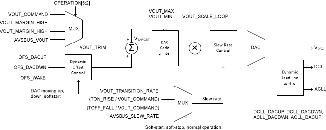
Figure 7-13 shows a conceptual view of the TPS53676 output voltage control, and dynamic behavior.
Update the VOUT_COMMAND value through PMBus, to change the output voltage of each channel on-the-fly. Optionally, use the OPERATION command to toggle the output voltage bewteen the VOUT_MARGIN_HIGH, VOUT_MARGIN_LOW and VOUT_COMMAND values. This is described in more detail in Section 7.5.2. AVSBus may also control the output voltage and slew rate when configured to do so through OPERATION.
The VOUT_MAX and VOUT_MIN commands define the maximum and minimum allowed voltage, through any combination of offsets and voltage target commands. If commanded higher or lower than these limits, the output voltage transitions to these limits and stops.
The soft-start and soft-stop slew rates are calculated using the current output voltage target and TON_RISE and TOFF_FALL command values. All output voltage transitions which occur during normal power conversion follow the slew rate defined by VOUT_TRANSITION_RATE.
The VOUT_SCALE_LOOP parameter must be set properly, when an external output voltage divider is being used. This value is used internally to provide scaling for all output voltage related parameters.
Update the VOUT_TRIM value to apply a static offset to the output voltage target. This may be used to fine-tune the output voltage in production, or null any board related offsets.
 Figure 7-13 Output voltage control conceptual view
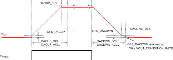
TPS53676 provides several options to fine-tune the controller response to high speed output voltage transitions. For example, large output voltage steps upward cause an inrush current, required to charge the output capacitors for that channel. This inrush current combined with the DC load line setting make the output voltage appear to move more slowly than the commanded slew rate. Use the DVID_CONFIG command to configure dynamic loadlines and offsets which apply only during output voltage transitions. Typically, set the DC and AC load lines for upward moving transitions to a value equal or lower than the nominal. Similarly, typically, set the DC and AC loadlines to a value larger than the nominal value for downward moving transitions. Refer to the Technical Reference Manual for a register map of this command.
 Figure 7-14 Dynamic load line and offset control
The DVID_CONFIG command also allows the user to configure dynamic offsets which are only applied during output voltage transitions. The configured recovery delays determine when the load line and offset values return to nominal settings, in terms of PWM (order 0) cycle counts. Figure 7-14 illustrates the dynamic load line, offset and recovery delay behavior of the controller.