SLUSCT1B June 2017 – January 2019 TPS53681
PRODUCTION DATA.
- 1 Features
- 2 Applications
- 3 Description
- 4 Revision History
- 5 Pin Configuration and Functions
-
6 Specifications
- 6.1 Absolute Maximum Ratings
- 6.2 ESD Ratings
- 6.3 Recommended Operating Conditions
- 6.4 Thermal Information
- 6.5 Supply: Currents, UVLO, and Power-On Reset
- 6.6 References: DAC and VREF
- 6.7 Voltage Sense: AVSP and BVSP, AVSN and BVSN
- 6.8 Telemetry
- 6.9 Input Current Sensing
- 6.10 Programmable Loadline Settings
- 6.11 Current Sense and Calibration
- 6.12 Logic Interface Pins: AVR_EN, AVR_RDY, BVR_EN, BVR_RDY, RESET, VR_FAULT, VR_HOT
- 6.13 I/O Timing
- 6.14 PMBus Address Setting
- 6.15 Overcurrent Limit Thresholds
- 6.16 Switching Frequency
- 6.17 Slew Rate Settings
- 6.18 Ramp Selections
- 6.19 Dynamic Integration and Undershoot Reduction
- 6.20 Boot Voltage and TMAX Settings
- 6.21 Protections: OVP and UVP
- 6.22 Protections: ATSEN and BTSEN Pin Voltage Levels and Fault
- 6.23 PWM: I/O Voltage and Current
- 6.24 Dynamic Phase Add and Drop
- 6.25 Typical Characteristics
-
7 Detailed Description
- 7.1 Overview
- 7.2 Functional Block Diagram
- 7.3 Feature Description
- 7.4 Device Functional Modes
- 7.5
Programming
- 7.5.1 PMBus Connections
- 7.5.2 PMBus Address Selection
- 7.5.3 Supported Commands
- 7.5.4 Commonly Used PMBus Commands
- 7.5.5 Voltage, Current, Power, and Temperature Readings
- 7.5.6 Input Current Sense and Calibration
- 7.5.7 Output Current Sense and Calibration
- 7.5.8 Output Voltage Margin Testing
- 7.5.9 Loop Compensation
- 7.5.10 Converter Protection and Response
- 7.5.11 Output Overvoltage Protection and Response
- 7.5.12 Maximum Allowed Output Voltage Setting
- 7.5.13 Output Undervoltage Protection and Response
- 7.5.14 Minimum Allowed Output Voltage Setting
- 7.5.15 Output Overcurrent Protection and Response
- 7.5.16 Input Under-Voltage Lockout (UVLO)
- 7.5.17 Input Over-Voltage Protection and Response
- 7.5.18 Input Undervoltage Protection and Response
- 7.5.19 Input Overcurrent Protection and Response
- 7.5.20 Over-Temperature Protection and Response
- 7.5.21 Dynamic Phase Shedding (DPS)
- 7.5.22 NVM Programming
- 7.5.23 NVM Security
- 7.5.24 Black Box Recording
- 7.5.25 Board Identification and Inventory Tracking
- 7.5.26 Status Reporting
-
8 Applications, Implementation, and Layout
- 8.1 Application Information
- 8.2 Typical Application
- 9 Power Supply Recommendations
- 10Layout
- 11Device and Documentation Support
- 12Mechanical, Packaging, and Orderable Information
Package Options
Mechanical Data (Package|Pins)
- RSB|40
Thermal pad, mechanical data (Package|Pins)
- RSB|40
Orderable Information
7.3.1.2 Load Transitions
When there is a sudden load increase, the output voltage immediately drops. The TPS53681 device reacts to this drop in a rising voltage on the COMP pin. This rise forces the PWM pulses to come in sooner and more frequently which causes the inductor current to rapidly increase. As the inductor current reaches the new load current, the device reaches a steady-state operating condition and the PWM switching resumes the steady-state frequency.
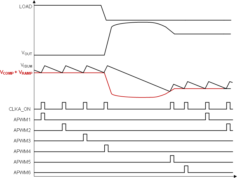
When there is a sudden load release, the output voltage flies high. The TPS53681 device reacts to this rise in a falling voltage on the COMP pin. This drop forces the PWM pulses to be delayed until the inductor current reaches the new load current. At that point, the switching resumes and steady-state switching continues.
Please note in Figure 7 and Figure 8, the ripples on VOUT, VRAMP, and VCOMP voltages are not shown for simplicity.
 Figure 7. Load Insertion
  Figure 8. Load Release
 The TPS53681 achieves fast load transient performance using the inherent variable switching frequency characteristics.Figure 7 illustrates the load insertion behavior that the PWM pulses can be generated with faster frequency than the steady-state frequency to provide more energy to improve the undershoot performance. Figure 8 illustrates the load release behavior that PWM pulses can be gated to avoid charging extra energy to the load until the output voltage reaches the peak overshoot.