-
TPS54418 2.95-V to 6-V Input, 4-A Output, 2-MHz, Synchronous Step-Down SWIFT™ Converter
- 1 Features
- 2 Applications
- 3 Description
- 4 Revision History
- 5 Pin Configuration and Functions
- 6 Specifications
-
7 Detailed Description
- 7.1 Overview
- 7.2 Functional Block Diagram
- 7.3
Feature Description
- 7.3.1 Fixed Frequency PWM Control
- 7.3.2 Slope Compensation and Output Current
- 7.3.3 Bootstrap Voltage (Boot) and Low Dropout Operation
- 7.3.4 Error Amplifier
- 7.3.5 Voltage Reference
- 7.3.6 Adjusting the Output Voltage
- 7.3.7 Enable and Adjusting Undervoltage Lockout
- 7.3.8 Soft-Start Pin
- 7.3.9 Sequencing
- 7.3.10 Constant Switching Frequency and Timing Resistor (RT/CLK Pin)
- 7.3.11 Overcurrent Protection
- 7.3.12 Frequency Shift
- 7.3.13 Reverse Overcurrent Protection
- 7.3.14 Synchronize Using the RT/CLK Pin
- 7.3.15 Power Good (PWRGD Pin)
- 7.3.16 Overvoltage Transient Protection
- 7.3.17 Thermal Shutdown
- 7.4 Device Functional Modes
-
8 Application and Implementation
- 8.1 Application Information
- 8.2
Typical Application
- 8.2.1 Design Requirements
- 8.2.2
Detailed Design Procedure
- 8.2.2.1 Step One: Select the Switching Frequency
- 8.2.2.2 Step Two: Select the Output Inductor
- 8.2.2.3 Step Three: Choose the Output Capacitor
- 8.2.2.4 Step Four: Select the Input Capacitor
- 8.2.2.5 Step Five: Minimum Load DC COMP Voltage
- 8.2.2.6 Step Six: Choose the Soft-Start Capacitor
- 8.2.2.7 Step Seven: Select the Bootstrap Capacitor
- 8.2.2.8 Step Eight: Undervoltage Lockout Threshold
- 8.2.2.9 Step Nine: Select Output Voltage and Feedback Resistors
- 8.2.2.10 Step 10: Select Loop Compensation Components
- 8.2.2.11 Power Dissipation Estimate
- 8.2.3 Application Curves
- 9 Power Supply Recommendations
- 10Layout
- 11Device and Documentation Support
- 12Mechanical, Packaging, and Orderable Information
- IMPORTANT NOTICE
Package Options
Mechanical Data (Package|Pins)
- RTE|16
Thermal pad, mechanical data (Package|Pins)
- RTE|16
Orderable Information
TPS54418 2.95-V to 6-V Input, 4-A Output, 2-MHz, Synchronous Step-Down SWIFT™ Converter
1 Features
- Two, 30-mΩ (typical) MOSFETs for High-Efficiency at 4-A loads
- Switching Frequency: 200 kHz to 2 MHz
- Voltage Reference Over Temperature: 0.8 V ± 1%
- Synchronizes to External Clock
- Adjustable Soft Start/Sequencing
- UV and OV Power-Good Output
- Low Operating and Shutdown Quiescent Current
- Safe Start-Up into Prebiased Output
- Cycle-by-Cycle Current Limit, Thermal and Frequency Foldback Protection
- Operating Junction Temperature Range: –40°C to 150°C
- Thermally Enhanced 3 mm × 3 mm 16-pin WQFN Package
- Create a Custom Design Using the TPS54418 With the WEBENCH® Power Designer
2 Applications
- Low-Voltage, High-Density Power Systems
- Point-of-Load Regulation for High Performance DSPs, FPGAs, ASICs and Microprocessors
- Broadband, Networking and Optical Communications Infrastructure
3 Description
TheTPS54418 device is a full-featured, 6-V, 4-A, synchronous, step-down current-mode converter with two integrated MOSFETs.
The TPS54418 device enables small designs by integrating the MOSFETs, implementing current mode control to reduce external component count, reducing inductor size by enabling up to 2-MHz switching frequency, and minimizing the device footprint with a small, 3 mm x 3 mm, thermally enhanced, QFN package.
The TPS54418 device provides accurate regulation for a variety of loads with an accurate ±1% voltage reference (VREF) over temperature.
Efficiency is maximized through the integrated 30-mΩ MOSFETs and a 350-μA typical supply current. Using the EN pin, shutdown supply current is reduced to 2 μA by entering a shutdown mode.
Undervoltage lockout is internally set at 2.6 V, but can be increased by programming the threshold with a resistor network on the enable pin. The output voltage startup ramp is controlled by the soft-start pin. An open-drain power-good signal indicates the output is within 93% to 107% of its nominal voltage. Frequency foldback and thermal shutdown protects the device during an overcurrent condition.
For more SWIFT™ documentation, see the TI website at www.ti.com/swift.
Device Information(1)
| PART NUMBER | PACKAGE | BODY SIZE (NOM) |
|---|---|---|
| TPS54418 | WQFN (16) | 3.00 mm × 3.00 mm |
- For all available packages, see the orderable addendum at the end of the datasheet.
Device Images
Simplified Schematic

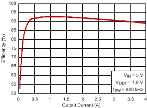
Efficiency vs Output Current

4 Revision History
Changes from D Revision (December 2014) to E Revision
- update title Go
Changes from C Revision (July 2013) to D Revision
- Added ESD Ratings table, Feature Description section, Device Functional Modes section, Application and Implementation section, Power Supply Recommendations section, Layout section, Device and Documentation Support section, and Mechanical, Packaging, and Orderable Information section Go
Changes from B Revision (August 2012) to C Revision
- Added Figure 22 to Typical Characteristics sectionGo
- Added clarity to Fixed Frequency PWM Control sectionGo
- Added clarity to Soft-Start Pin sectionGo
- Added clarity to Synchronize Using the RT/CLK Pin sectionGo
- Added Step Five: Minimum Load DC COMP Voltage sectionGo
- Added clarity to the Step Six: Choose the Soft-Start Capacitor sectionGo
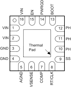
5 Pin Configuration and Functions

Pin Functions
| PIN | I/O(1) | DESCRIPTION | |
|---|---|---|---|
| NAME | NO. | ||
| AGND | 5 | G | Analog ground should be electrically connected to GND close to the device. |
| BOOT | 13 | I | A bootstrap capacitor is required between BOOT and PH. If the voltage on this capacitor is below the minimum required by the BOOT UVLO, the output is forced to switch off until the capacitor is refreshed. |
| COMP | 7 | O | Error amplifier output, and input to the output switch current comparator. Connect frequency compensation components to this pin. |
| EN | 15 | I | Enable pin, internal pull-up current source. Pull below 1.2 V to disable. Float to enable. Can be used to set the on/off threshold (adjust UVLO) with two additional resistors. |
| GND | 3 | G | Power ground. This pin should be electrically connected directly to the power pad under the device. |
| 4 | |||
| PH | 10 | O | The source of the internal high-side power MOSFET, and drain of the internal low-side (synchronous) rectifier MOSFET. |
| 11 | |||
| 12 | |||
| PWRGD | 14 | O | An open drain output, asserts low if output voltage is low due to thermal shutdown, overcurrent, over/under-voltage or EN shut down. |
| RT/CLK | 8 | I/O | Resistor Timing or External Clock input pin. |
| SS | 9 | I/O | Slow-start. An external capacitor connected to this pin sets the output voltage rise time. Soft |
| VIN | 1 | I | Input supply voltage, 2.95 V to 6 V. |
| 2 | |||
| 16 | |||
| VSENSE | 6 | I | Inverting node of the transconductance (gm) error amplifier. |
| Thermal Pad | G | GND pin should be connected to the exposed power pad for proper operation. This power pad should be connected to any internal PCB ground plane using multiple vias for good thermal performance. | |