SLUSF27 November 2023 TPS546B24S
PRODUCTION DATA
- 1
- 1 Features
- 2 Applications
- 3 Description
- 4 Pin Configuration and Functions
- 5 Specifications
-
6 Detailed Description
- 6.1 Overview
- 6.2 Functional Block Diagram
- 6.3
Feature Description
- 6.3.1 Average Current-Mode Control
- 6.3.2 Linear Regulators
- 6.3.3 AVIN and PVIN Pins
- 6.3.4 Input Undervoltage Lockout (UVLO)
- 6.3.5 Start-Up and Shutdown
- 6.3.6 Differential Sense Amplifier and Feedback Divider
- 6.3.7 Set Output Voltage and Adaptive Voltage Scaling (AVS)
- 6.3.8 Prebiased Output Start-Up
- 6.3.9 Soft Stop and (65h) TOFF_FALL Command
- 6.3.10 Power Good (PGOOD)
- 6.3.11 Set Switching Frequency
- 6.3.12 Frequency Synchronization
- 6.3.13 Loop Follower Detection
- 6.3.14 Current Sensing and Sharing
- 6.3.15 Telemetry
- 6.3.16 Overcurrent Protection
- 6.3.17 Overvoltage/Undervoltage Protection
- 6.3.18 Overtemperature Management
- 6.3.19 Fault Management
- 6.3.20 Back-Channel Communication
- 6.3.21 Switching Node (SW)
- 6.3.22 PMBus General Description
- 6.3.23 PMBus Address
- 6.3.24 PMBus Connections
- 6.4 Device Functional Modes
- 6.5 Programming
- 6.6
Register Maps
- 6.6.1 Conventions for Documenting Block Commands
- 6.6.2 (01h) OPERATION
- 6.6.3 (02h) ON_OFF_CONFIG
- 6.6.4 (03h) CLEAR_FAULTS
- 6.6.5 (04h) PHASE
- 6.6.6 (10h) WRITE_PROTECT
- 6.6.7 (15h) STORE_USER_ALL
- 6.6.8 (16h) RESTORE_USER_ALL
- 6.6.9 (19h) CAPABILITY
- 6.6.10 (1Bh) SMBALERT_MASK
- 6.6.11 (1Bh) SMBALERT_MASK_VOUT
- 6.6.12 (1Bh) SMBALERT_MASK_IOUT
- 6.6.13 (1Bh) SMBALERT_MASK_INPUT
- 6.6.14 (1Bh) SMBALERT_MASK_TEMPERATURE
- 6.6.15 (1Bh) SMBALERT_MASK_CML
- 6.6.16 (1Bh) SMBALERT_MASK_OTHER
- 6.6.17 (1Bh) SMBALERT_MASK_MFR
- 6.6.18 (20h) VOUT_MODE
- 6.6.19 (21h) VOUT_COMMAND
- 6.6.20 (22h) VOUT_TRIM
- 6.6.21 (24h) VOUT_MAX
- 6.6.22 (25h) VOUT_MARGIN_HIGH
- 6.6.23 (26h) VOUT_MARGIN_LOW
- 6.6.24 (27h) VOUT_TRANSITION_RATE
- 6.6.25 (29h) VOUT_SCALE_LOOP
- 6.6.26 (2Bh) VOUT_MIN
- 6.6.27 (33h) FREQUENCY_SWITCH
- 6.6.28 (35h) VIN_ON
- 6.6.29 (36h) VIN_OFF
- 6.6.30 (37h) INTERLEAVE
- 6.6.31 (38h) IOUT_CAL_GAIN
- 6.6.32 (39h) IOUT_CAL_OFFSET
- 6.6.33 (40h) VOUT_OV_FAULT_LIMIT
- 6.6.34 (41h) VOUT_OV_FAULT_RESPONSE
- 6.6.35 (42h) VOUT_OV_WARN_LIMIT
- 6.6.36 (43h) VOUT_UV_WARN_LIMIT
- 6.6.37 (44h) VOUT_UV_FAULT_LIMIT
- 6.6.38 (45h) VOUT_UV_FAULT_RESPONSE
- 6.6.39 (46h) IOUT_OC_FAULT_LIMIT
- 6.6.40 (47h) IOUT_OC_FAULT_RESPONSE
- 6.6.41 (4Ah) IOUT_OC_WARN_LIMIT
- 6.6.42 (4Fh) OT_FAULT_LIMIT
- 6.6.43 (50h) OT_FAULT_RESPONSE
- 6.6.44 (51h) OT_WARN_LIMIT
- 6.6.45 (55h) VIN_OV_FAULT_LIMIT
- 6.6.46 (56h) VIN_OV_FAULT_RESPONSE
- 6.6.47 (58h) VIN_UV_WARN_LIMIT
- 6.6.48 (60h) TON_DELAY
- 6.6.49 (61h) TON_RISE
- 6.6.50 (62h) TON_MAX_FAULT_LIMIT
- 6.6.51 (63h) TON_MAX_FAULT_RESPONSE
- 6.6.52 (64h) TOFF_DELAY
- 6.6.53 (65h) TOFF_FALL
- 6.6.54 (78h) STATUS_BYTE
- 6.6.55 (79h) STATUS_WORD
- 6.6.56 (7Ah) STATUS_VOUT
- 6.6.57 (7Bh) STATUS_IOUT
- 6.6.58 (7Ch) STATUS_INPUT
- 6.6.59 (7Dh) STATUS_TEMPERATURE
- 6.6.60 (7Eh) STATUS_CML
- 6.6.61 (7Fh) STATUS_OTHER
- 6.6.62 (80h) STATUS_MFR_SPECIFIC
- 6.6.63 (88h) READ_VIN
- 6.6.64 (8Bh) READ_VOUT
- 6.6.65 (8Ch) READ_IOUT
- 6.6.66 (8Dh) READ_TEMPERATURE_1
- 6.6.67 (98h) PMBUS_REVISION
- 6.6.68 (99h) MFR_ID
- 6.6.69 (9Ah) MFR_MODEL
- 6.6.70 (9Bh) MFR_REVISION
- 6.6.71 (9Eh) MFR_SERIAL
- 6.6.72 (ADh) IC_DEVICE_ID
- 6.6.73 (AEh) IC_DEVICE_REV
- 6.6.74 (B1h) USER_DATA_01 (COMPENSATION_CONFIG)
- 6.6.75 (B5h) USER_DATA_05 (POWER_STAGE_CONFIG)
- 6.6.76 (D0h) MFR_SPECIFIC_00 (TELEMETRY_CONFIG)
- 6.6.77 (DAh) MFR_SPECIFIC_10 (READ_ALL)
- 6.6.78 (DBh) MFR_SPECIFIC_11 (STATUS_ALL)
- 6.6.79 (DCh) MFR_SPECIFIC_12 (STATUS_PHASE)
- 6.6.80 (E3h) MFR_SPECIFIC_19 (PGOOD_CONFIG)
- 6.6.81 (E4h) MFR_SPECIFIC_20 (SYNC_CONFIG)
- 6.6.82 (ECh) MFR_SPECIFIC_28 (STACK_CONFIG)
- 6.6.83 (EDh) MFR_SPECIFIC_29 (MISC_OPTIONS)
- 6.6.84 (EEh) MFR_SPECIFIC_30 (PIN_DETECT_OVERRIDE)
- 6.6.85 (EFh) MFR_SPECIFIC_31 (DEVICE_ADDRESS)
- 6.6.86 (F0h) MFR_SPECIFIC_32 (NVM_CHECKSUM)
- 6.6.87 (F1h) MFR_SPECIFIC_33 (SIMULATE_FAULT)
- 6.6.88 (FAh) MFR_SPECIFIC_42 (PASSKEY)
- 6.6.89 (FBh) MFR_SPECIFIC_43 (EXT_WRITE_PROTECT)
- 6.6.90 (FCh) MFR_SPECIFIC_44 (FUSION_ID0)
- 6.6.91 (FDh) MFR_SPECIFIC_45 (FUSION_ID1)
-
7 Application and Implementation
- 7.1 Application Information
- 7.2
Typical Application
- 7.2.1 Design Requirements
- 7.2.2
Detailed Design Procedure
- 7.2.2.1 Custom Design With WEBENCH® Tools
- 7.2.2.2 Switching Frequency
- 7.2.2.3 Inductor Selection
- 7.2.2.4 Output Capacitor Selection
- 7.2.2.5 Input Capacitor Selection
- 7.2.2.6 AVIN, BP1V5, VDD5 Bypass Capacitor
- 7.2.2.7 Bootstrap Capacitor Selection
- 7.2.2.8 R-C Snubber
- 7.2.2.9 Output Voltage Setting (VSEL Pin)
- 7.2.2.10 Compensation Selection (MSEL1 Pin)
- 7.2.2.11 Soft Start, Overcurrent Protection, and Stacking Configuration (MSEL2 Pin)
- 7.2.2.12 Enable and UVLO
- 7.2.2.13 ADRSEL
- 7.2.2.14 Pin-Strapping Resistor Selection
- 7.2.2.15 BCX_CLK and BCX_DAT
- 7.2.3 Application Curves
- 7.3 Power Supply Recommendations
- 7.4 Layout
- 8 Device and Documentation Support
- 9 Revision History
- 10Mechanical, Packaging, and Orderable Information
Package Options
Mechanical Data (Package|Pins)
- RVF|40
Thermal pad, mechanical data (Package|Pins)
- RVF|40
Orderable Information
6.3.3 AVIN and PVIN Pins
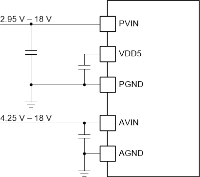
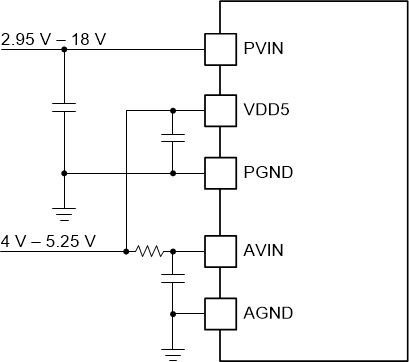
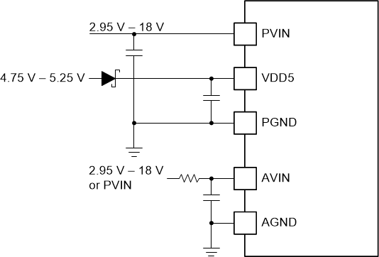
The device allows for a variety of applications by using the AVIN and PVIN pins together or separately. The AVIN pin voltage supplies the internal control circuits of the device. The PVIN pin voltage provides the input voltage to the switching power stage. When connected to a single supply, the input voltage for AVIN and PVIN can range from 4 V to 16 V. If the PVIN is connected to separate supply from AVIN, the PVIN voltage can be 2.95 V to 16 V, and AVIN has to meet 4-V minimum and 18-V maximum to drive the control and driver. If AVIN is connected to the same supply as PVIN or VDD5, TI recommends a minimum 10-µs R-C filter with a 1-Ω to 10-Ω resistor and AVIN bypass capacitor between AVIN and PVIN to reduce PVIN switching noise on the AVIN input.
 Figure 6-2 TPS546B24S Separate PVIN and AVIN Connections
 Figure 6-3 TPS546B24S Separate PVIN and AVIN Connections with VDD5
 Figure 6-4 TPS546B24S Separate PVIN, AVIN, and VDD5 Connections