SLVS258B
November 1999 – December 2016
TPS60130
,
TPS60131
,
TPS60132
,
TPS60133
PRODUCTION DATA.
1
Features
2
Applications
3
Description
4
Revision History
5
Device Options
6
Pin Configuration and Functions
7
Specifications
7.1
Absolute Maximum Ratings
7.2
ESD Ratings
7.3
Recommended Operating Conditions
7.4
Thermal Information
7.5
Electrical Characteristics
7.6
Dissipation Ratings
7.7
Typical Characteristics
8
Parameter Measurement Information
9
Detailed Description
9.1
Overview
9.2
Functional Block Diagram
9.3
Feature Description
9.3.1
Operating Principle
9.3.2
Adaptive Mode Switching
9.3.3
Pulse-Skip Mode
9.3.4
Start-Up Procedure
9.3.5
Shutdown
9.3.6
Undervoltage Lockout
9.3.7
Low Battery Detector (TPS60130 and TPS60132)
9.3.8
Power Good Detector (TPS60131 and TPS60133)
10
Application and Implementation
10.1
Application Information
10.2
Typical Applications
10.2.1
Paralleling of Two TPS6013x to Deliver 600-mA Total Output Current
10.2.1.1
Design Requirements
10.2.1.2
Detailed Design Procedure
10.2.1.2.1
Capacitor Selection
10.2.1.3
Application Curves
10.2.2
TPS6013x Operated With Ultra-Low Quiescent Current
10.2.2.1
Design Requirements
10.2.3
Regulated Discharge of the Output Capacitors After Disabling of the TPS6013x
10.2.3.1
Design Requirements
11
Power Supply Recommendations
12
Layout
12.1
Layout Guidelines
12.2
Layout Example
12.3
Power Dissipation
13
Device and Documentation Support
13.1
Documentation Support
13.1.1
Related Documentation
13.2
Related Links
13.3
Receiving Notification of Documentation Updates
13.4
Community Resources
13.5
Trademarks
13.6
Electrostatic Discharge Caution
13.7
Glossary
14
Mechanical, Packaging, and Orderable Information
Package Options
Mechanical Data (Package|Pins)
PWP|20
MHTS001G
Thermal pad, mechanical data (Package|Pins)
PWP|20
PPTD166L
Orderable Information
slvs258b_oa
slvs258b_pm
8
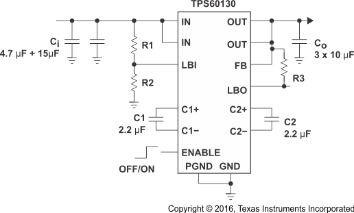
Parameter Measurement Information
Figure 18.
Circuit Used for Typical Characteristics Measurements