SLVS302B December 2000 – October 2015 TPS60300 , TPS60301 , TPS60302 , TPS60303
PRODUCTION DATA.
- 1 Features
- 2 Applications
- 3 Description
- 4 Revision History
- 5 Description (continued)
- 6 Device Comparison Table
- 7 Pin Configuration and Functions
- 8 Specifications
- 9 Detailed Description
- 10Application and Implementation
- 11Power Supply Recommendations
- 12Layout
- 13Device and Documentation Support
- 14Mechanical, Packaging, and Orderable Information
Package Options
Mechanical Data (Package|Pins)
- DGS|10
Thermal pad, mechanical data (Package|Pins)
Orderable Information
9 Detailed Description
9.1 Overview
The TPS6030x charge pumps are voltage quadruplers that provide a regulated 3.3-V or 3-V output from a
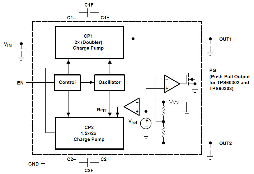
0.9-V to 1.8-V input. They deliver a maximum load current of 20 mA. Designed specifically for space critical battery powered applications, the complete converter requires only five external capacitors and enables the design to use low-cost, small-sized, 1-µF ceramic capacitors. The TPS6030x circuits consist of an oscillator, a voltage reference, an internal resistive feedback circuit, an error amplifier, two charge pump stages with MOSFET switches, a shutdown and start-up circuit, and a control circuit.
9.2 Functional Block Diagram

9.3 Feature Description
9.3.1 Power-Good Detector
The power-good output is an open-drain output on the TPS60300 and TPS60301 or a push-pull output on the TPS60302 and TPS60303. The PG-output pulls low when the output of OUT2 is out of regulation. When the output rises to within 98% of regulation, the power-good output goes active high. In shutdown, power-good is pulled low. In normal operation, an external pullup resistor with the TPS60300 and TPS60301 is typically used to connect the PG pin to VOUT. The resistor should be in the 100-kΩ to 1-MΩ range. If the PG output is not used, it should remain unconnected. Output current at PG (TPS60302, TPS60303) will reduce maximum output current at OUT2.
9.4 Device Functional Modes
9.4.1 Start-up Procedure
The device is enabled when EN is set from logic low to logic high. CP1 will first enter a DC start-up mode during which the capacitor on OUT1 is charged up to about VIN. After that, it starts switching to boost the voltage further up to about two times VIN. CP2 will then follow and charge up the capacitor on OUT2 to about the voltage on OUT1, after that, it will also start switching and boost up the voltage to its nominal value. EN must not exceed the highest voltage applied to the device.
NOTE
During start-up with VOUT = 0 V, the highest voltage is the input voltage.
9.4.2 Shutdown
Driving EN low disables the converter. This disables all internal circuits, reducing input current to only 0.05 µA. Leakage current drawn from the output pins OUT1 and OUT2 is a maximum of 1 µA. The device exits shutdown once EN is set high (see Start-up Procedure). The typical no-load, start-up time is 400 µs. When the device is disabled, the load is isolated from the input. This is an important feature in battery operated products because it extends the battery shelf life.