-
TPS61094 60-nA Quiescent Current Boost Converter with Supercap Management
- 1 Features
- 2 Applications
- 3 Description
- 4 Revision History
- 5 Pin Configuration and Functions
- 6 Specifications
- 7 Detailed Description
- 8 Application and Implementation
- 9 Power Supply Recommendations
- 10Layout
- 11Device and Documentation Support
- 12Mechanical, Packaging, and Orderable Information
- IMPORTANT NOTICE
Package Options
Mechanical Data (Package|Pins)
- DSS|12
Thermal pad, mechanical data (Package|Pins)
- DSS|12
Orderable Information
TPS61094 60-nA Quiescent Current Boost Converter with Supercap Management
1 Features
- Wide voltage range and current range
- 0.7-V to 5.5-V input voltage range
- 1.8-V minimum input voltage for start-up
- Programmable boost output voltages, 2.7-V to 5.4-V setting range
- Programmable buck charging termination voltages, 1.7-V to 5.4-V setting range
- Programmable buck charging output currents, 2.5-mA to 600-mA setting range
- Ultra-low quiescent current
- 60 nA in boost mode or buck charging mode
- 4 nA in forced bypass mode
- High efficiency and power capability
- Typical 2.0-A inductor valley current limit
- Two 60-mΩ (LS) / 140-mΩ (HS) MOSFETs
- 100-mΩ bypass switch resistance
- 1-MHz switching frequency
- Auto snooze mode operation at light load
- Up to 92.3% efficiency at VIN = 3 V, VOUT = 3.6 V, and IOUT = 10 μA
- Up to 96.3% efficiency at VIN = 3 V, VOUT = 3.6 V, and IOUT = 100 mA
- Four operation modes controlled by the MODE and EN pins
- Rich protection
- Output short-circuit protection
- Thermal shutdown protection
- 2-mm × 3-mm 12-pin WSON package
2 Applications
3 Description
The TPS61094 is a 60-nA IQ boost converter with supercap management. The device provides a power supply solution for smart meter and super capacitor backup power applications.
The TPS61094 has a wide input voltage range and output voltage up to 5.5 V. When the TPS61094 works in buck mode and charges the supercap, the charging current and the termination voltage are programmable with two external resistors. When the TPS61094 works in boost mode, the output voltage is programmable with an external resistor.
During automatic buck or boost mode (EN = 1, MODE = 1), when the input power supply is applied, the device bypasses the input voltage to the output while it is capable of charging a backup supercap. When the input power supply is disconnected or lower than the output target voltage, the TPS61094 enters boost mode and regulates output voltage from a backup supercap. The TPS61094 consumes 60-nA quiescent current in this mode.
The TPS61094 supports true shutdown mode (EN = 0, MODE = 1) and the forced bypass mode (EN = 0, MODE = 0). In true shutdown mode, the TPS61094 completely disconnects the load from the input supply. When supporting forced bypass mode, the TPS61094 connects the load to the input voltage directly through a bypass switch and only consumes 4-nA current to achieve long battery life.
| PART NUMBER | PACKAGE(1) | BODY SIZE (NOM) |
|---|---|---|
| TPS61094 | WSON (12) | 2.0 mm × 3.0 mm |
 Typical Application Circuit 2
4 Revision History
Changes from Revision B (September 2021) to Revision C (December 2021)
- Changed the title Go
- Updated the typical applicationGo
- Changed "Minimum 1.4-A inductor valley current limit" to "Typical 2.0-A inductor valley current"Go
- Updated Section 3 Go
- Add the description about the quiescent current at pass through modeGo
Changes from Revision A (February 2021) to Revision B (September 2021)
- Changed document status from Advance Information to Production DataGo
5 Pin Configuration and Functions
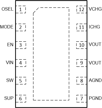
 Figure 5-1 12-Pin WSONDSS Package(Top View)
| PIN | I/O(1) | DESCRIPTION | |
|---|---|---|---|
| NO. | NAME | ||
| 1 | OSEL | I | Boost output voltage selection pin. Connect a resistor between this pin and ground to select one of sixteen output voltages of Boost mode. |
| 2 | MODE | I | Operation mode selection pin. The MODE pin and EN pin work together to set device operation mode. See Table 7-4. |
| 3 | EN | I | Operation mode selection pin. The MODE pin and EN pin work together to set device operation mode. See Table 7-4. |
| 4 | VIN | PWR | IC power supply input |
| 5 | SW | PWR | The switching node pin of the converter. It is connected to the drain of the internal low-side power MOSFET and the source of the internal high-side power MOSFET. |
| 6 | SUP | I | Output of buck converter to sense the voltage of the supercap |
| 7 | PGND | PWR | Power ground |
| 8 | AGND | PWR | Signal ground |
| 9, 10 | VOUT | PWR | Output of the device |
| 11 | ICHG | I | Charging current selection pin. Connect a resistor between this pin and ground to select one of sixteen output currents of Buck mode. |
| 12 | VCHG | I | Charging voltage selection pin. Connect a resistor between this pin and ground to select one of sixteen regulation voltages of Buck mode. |