SLVS790E November   2007  – April 2019 TPS61165

PRODUCTION DATA.  

  1. Features
  2. Applications
  3. Description
    1.     Device Images
      1.      Typical Application
  4. Revision History
  5. Device Options
  6. Pin Configuration and Functions
    1.     Pin Functions
  7. Specifications
    1. 7.1 Absolute Maximum Ratings
    2. 7.2 Recommended Operating Conditions
    3. 7.3 Thermal Information
    4. 7.4 Electrical Characteristics
    5. 7.5 Timing Requirements
    6. 7.6 Typical Characteristics
  8. Detailed Description
    1. 8.1 Overview
    2. 8.2 Functional Block Diagram
    3. 8.3 Feature Description
      1. 8.3.1 Soft Start-Up
      2. 8.3.2 Open LED Protection
      3. 8.3.3 Undervoltage Lockout
      4. 8.3.4 Thermal Shutdown
    4. 8.4 Device Functional Modes
      1. 8.4.1 Shutdown
  9. Application and Implementation
    1. 9.1 Application Information
      1. 9.1.1 Maximum Output Current
      2. 9.1.2 Inductor Selection
      3. 9.1.3 Schottky Diode Selection
      4. 9.1.4 Compensation Capacitor Selection
      5. 9.1.5 Input and Output Capacitor Selection
    2. 9.2 Typical Applications
      1. 9.2.1 TPS61165 Typical Application
        1. 9.2.1.1 Design Requirements
        2. 9.2.1.2 Detailed Design Procedure
          1. 9.2.1.2.1 LED Brightness Dimming Mode Selection
          2. 9.2.1.2.2 PWM Brightness Dimming
          3. 9.2.1.2.3 Digital One-Wire Brightness Dimming
          4. 9.2.1.2.4 EasyScale: One-Wire Digital Dimming
          5. 9.2.1.2.5 Current Program
        3. 9.2.1.3 Application Curves
      2. 9.2.2 Additional Application Circuits
    3. 9.3 Do's and Don'ts
  10. 10Power Supply Recommendations
  11. 11Layout
    1. 11.1 Layout Guidelines
    2. 11.2 Layout Example
    3. 11.3 Thermal Considerations
  12. 12Device and Documentation Support
    1. 12.1 Device Support
      1. 12.1.1 Third-Party Products Disclaimer
    2. 12.2 Documentation Support
      1. 12.2.1 Related Documentation
    3. 12.3 Community Resources
    4. 12.4 Trademarks
    5. 12.5 Electrostatic Discharge Caution
    6. 12.6 Glossary
  13. 13Mechanical, Packaging, and Orderable Information

Package Options

Mechanical Data (Package|Pins)
Thermal pad, mechanical data (Package|Pins)
Orderable Information

Additional Application Circuits

The TPS61165 can be configured to drive three high-brightness LEDs using an external PWM dimming network. Figure 16 shows an example application circuit.

TPS61165 dvr_3_hi_lvs790.gifFigure 16. Drive Three High-Brightness LEDs With External PWM Dimming Network

The TPS61165 can be configured to drive nine strings of three LEDs for media form factor displays. Figure 17 shows an example application circuit.
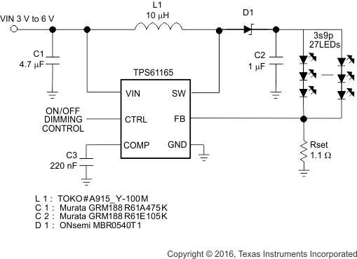
TPS61165 dvr_27_led_lvs790.gifFigure 17. Drive 27 LEDs for Media Form-Factor Display

The TPS61165 can be configured to drive six high-brightness LEDs in series. Figure 18 provides an example applications circuit.

TPS61165 dvr_6_hi_lvs790.gifFigure 18. Drive Six High-Brightness LEDs

The TPS61165 can be configured to drive four high-brightness LEDs using SEPIC topology. An example application circuit can be found in Figure 19.

TPS61165 dvr_4_hi_lvs790.gifFigure 19. Drive Four High-Brightness LED With SEPIC Topology