SLVS417F March 2002 – June 2015 TPS62200 , TPS62201 , TPS62202 , TPS62203 , TPS62204 , TPS62205 , TPS62207 , TPS62208
PRODUCTION DATA.
- 1 Features
- 2 Applications
- 3 Description
- 4 Revision History
- 5 Pin Configuration and Functions
- 6 Specifications
- 7 Detailed Description
- 8 Application and Implementation
- 9 Power Supply Recommendations
- 10Layout
- 11Device and Documentation Support
- 12Mechanical, Packaging, and Orderable Information
Package Options
Refer to the PDF data sheet for device specific package drawings
Mechanical Data (Package|Pins)
- DBV|5
Thermal pad, mechanical data (Package|Pins)
Orderable Information
10 Layout
10.1 Layout Guidelines
- For all switching power supplies, the layout is an important step in the design, especially at high peak currents and switching frequencies. If the layout is not carefully done, the regulator shows stability problems as well as EMI problems.
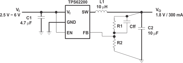
- Therefore use wide and short traces for the main current paths, as indicated in bold in Figure 19. The input capacitor should be placed as close as possible to the IC pins.
- The feedback resistor network must be routed away from the inductor and switch node to minimize noise and magnetic interference. To further minimize noise from coupling into the feedback network and feedback pin, the ground plane or ground traces must be used for shielding. This becomes very important especially at high switching frequencies of 1 MHz.
10.2 Layout Example
 Figure 19. Layout Diagram