SLVSG71 june 2023 TPS62901-Q1
PRODUCTION DATA
- 1
- 1 Features
- 2 Applications
- 3 Description
- 4 Revision History
- 5 Device Comparison Table
- 6 Pin Configuration and Functions
- 7 Specifications
-
8 Detailed Description
- 8.1 Overview
- 8.2 Functional Block Diagram
- 8.3
Feature Description
- 8.3.1 Mode Selection and Device Configuration MODE/S-CONF
- 8.3.2 Adjustable VO Operation (External Voltage Divider)
- 8.3.3 Selectable VO Operation (VSET and Internal Voltage Divider)
- 8.3.4 Soft Start and Tracking (SS/TR)
- 8.3.5 Smart Enable with Precise Threshold
- 8.3.6 Power Good (PG)
- 8.3.7 Output Discharge Function
- 8.3.8 Undervoltage Lockout (UVLO)
- 8.3.9 Current Limit and Short-Circuit Protection
- 8.3.10 High Temperature Specifications
- 8.3.11 Thermal Shutdown
- 8.4 Device Functional Modes
-
9 Application and Implementation
- 9.1 Application Information
- 9.2 Typical Application with Adjustable Output Voltage
- 9.3 Typical Application with Selectable VOUT using VSET
- 9.4 System Examples
- 9.5 Power Supply Recommendations
- 9.6 Layout
- 10Device and Documentation Support
- 11Mechanical, Packaging, and Orderable Information
Package Options
Mechanical Data (Package|Pins)
- RYT|9
Thermal pad, mechanical data (Package|Pins)
Orderable Information
9.4.3 Voltage Tracking
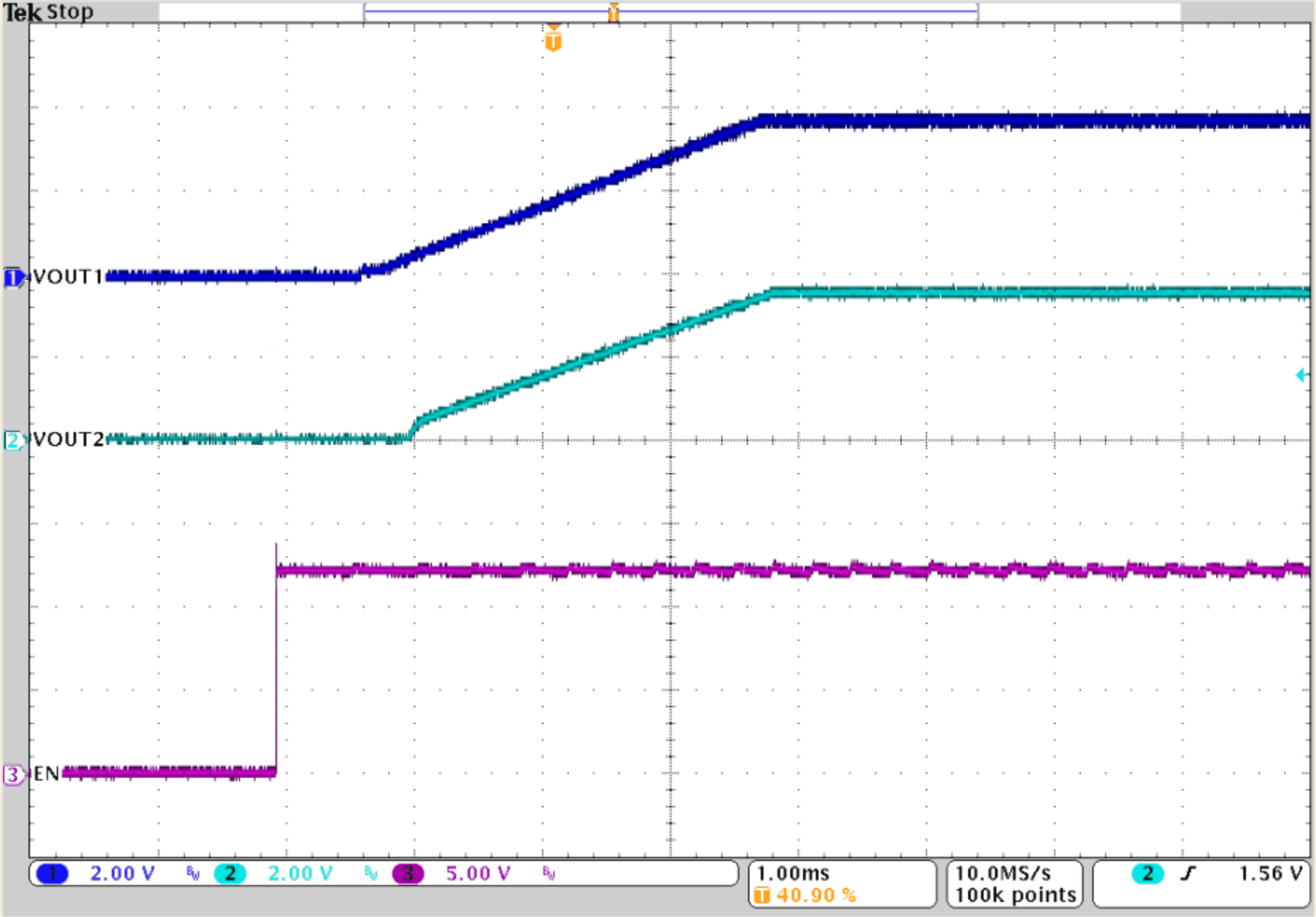
Figure 9-66 shows how two TPS62901-Q1s can be configured to tracking output voltages. In this configuration, Device 2 follows the voltage applied to its SS/TR pin from Device 1 output. A ramp on the SS/TR pin of Device 2 to 0.8 V in turn ramps VOUT2 according to the 0.6-V reference on VFB and the R4//R5 resistor divider.
For this example, to track the 3.8 V (VOUT1) of Device 1 a resistor divider (R7//R8) on SS/TR of Device 2 is required to generate 0.8 V when the output voltage (VOUT1) is in regulation. Due to the ISS current of 2.5 µA from the SS/TR pin, the equivalent resistance of R7 // R8 must be kept below 15 kΩ to minimize any offset the ISS current can cause on the SS/TR pin voltage.
 Figure 9-66 Tracking
Example
 Figure 9-67 Tracking