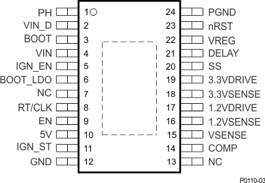
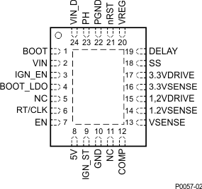
| 1.2VDRIVE |
17 |
15 |
O |
Output current source to drive the base of an external bipolar transistor to regulate the 1.234-V supply |
| 1.2VSENSE |
16 |
14 |
I |
Voltage node of 1.234-V supply |
| 3.3VDRIVE |
19 |
17 |
O |
Output current source to drive the base of an external bipolar transistor to regulate the 3.3-V supply |
| 3.3VSENSE |
18 |
16 |
I |
Voltage node of 3.3-V supply |
| 5V |
10 |
8 |
O |
External capacitor to ground for stability of regulated output |
| BOOT |
3 |
1 |
O |
External bootstrap capacitor connected to PH (pin 1) to drive gate of internal switching FET |
| BOOT_LDO |
6 |
4 |
O |
External capacitor connected to ground for stability of internal regulator |
| COMP |
14 |
12 |
O |
Error amplifier output to connect external compensation components |
| DELAY |
21 |
19 |
O |
External capacitor to ground to program the power-on-reset delay |
| EN |
9 |
7 |
I |
A high logic-level input signal to enable and low signal to disable device. Internally pulled down to ground |
| GND |
12 |
10 |
O |
Ground pin, must be electrically connected to exposed pad on PCB for proper thermal performance |
| IGN_EN |
5 |
3 |
I |
Ignition input (high-voltage tolerant) internally pulls to ground. Must be externally pulled up to enable |
| IGN_ST |
11 |
9 |
O |
Active-low, open-drain ignition input indicator, output connected to external bias voltage through a resistor. Asserted high after ignition input is high |
| NC |
7 |
5 |
— |
Connect to ground |
| 13 |
11 |
| nRST |
23 |
21 |
O |
Active-low, open-drain reset output connected to external bias voltage through a resistor. This output is asserted high after the preregulator, 3.3-V, and 1.234-V regulator outputs are regulating and the delay timer has expired. Also, output is asserted low if any one of these three supplies is out of the set regulation, this threshold is internally set. |
| PGND |
24 |
22 |
O |
Power ground pin, must be electrically connected to exposed pad on PCB for proper thermal performance |
| PH |
1 |
23 |
O |
Source of internal switching FET |
| RT/CLK |
8 |
6 |
I/O |
External resistor connected ground to program the internal oscillator. Alternative option is to feed an external clock to provide reference for switching frequency. |
| SS |
20 |
18 |
O |
External capacitor to ground to program soft-start time |
| VIN |
4 |
2 |
I |
Unregulated input voltage supply. Pins 2 and 4 must be connected together externally. |
| VIN_D |
2 |
24 |
I |
Drain input for internal high-side MOSFET. Pins 2 and 4 must be connected together externally. |
| VREG |
22 |
20 |
I |
Buck converter output. Integrated internal low-side FET to load output during startup or limit voltage overshoot |
| VSENSE |
15 |
13 |
I |
Inverting node of error amplifier for voltage-mode control of preregulated supply |
| Thermal pad |
— |
Electrically connect to ground and solder to ground plane of PCB for thermal efficiency |

