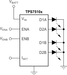
Refer to the PDF data sheet for device specific package drawings
The TPS7510x linear low dropout (LDO) matching LED current source is optimized for low-power keypad and navigation pad LED backlighting applications. The device provides a constant current to up to four unmatched LEDs organized in two banks of two LEDs each in a common-cathode topology. Without an external resistor, the current source defaults to a factory-programmable, preset current level with ±0.5% accuracy (typical). An optional external resistor can be used to set initial brightness to user-programmable values with higher accuracy. Brightness can be varied from off to full brightness by inputting a pulse width modulation (PWM) signal on each enable pin (ENx, where x indicates LED bank A or B). Each bank has independent enable and brightness control, but current matching is done to all four channels concurrently. The input supply range is ideally suited for single-cell Li-Ion battery supplies and the TPS7510x can provide up to 25 mA per LED.
No internal switching signals are used, eliminating troublesome electromagnetic interference (EMI). The TPS7510x is offered in an ultra-small, 9-ball, 0.4-mm ball-pitch wafer chip-scale package (WCSP) and a 2.50-mm × 2.50-mm, 10-pin WSON package, yielding a very compact total solution size ideal for mobile handsets and portable backlighting applications. The device is fully specified over TJ = –40°C to +85°C.
PART NUMBER | PACKAGE | BODY SIZE (NOM) |
---|---|---|
TPS7510x | WSON (10) | 2.50 mm × 2.50 mm |
DSBGA (9) | 1.208 mm x 1.208 mm |
Changes from I Revision (November 2013) to J Revision
Changes from H Revision (January 2010) to I Revision
Changes from G Revision (March 2009) to H Revision
PIN | I/O | DESCRIPTION | ||
---|---|---|---|---|
NAME | WCSP | WSON | ||
ENA | A3 | 2 | I | Enable pin, Bank A. Driving this pin high turns on the current source to Bank A outputs. Driving this pin low turns off the current source to Bank A outputs. An applied PWM signal reduces the LED current (between 0 mA and the maximum current set by ISET) as a function of the duty cycle of the PWM signal. ENA and ENB can be tied together. ENA can be left OPEN or connected to GND if not used. See the Application and Implementation section for more details. |
D1A | B3 | 3 | O | Diode source current output, Bank A. Connect to LED anode. |
D2A | C3 | 4 | O | Diode source current output, Bank A. Connect to LED anode. |
ENB | A2 | 1 | I | Enable pin, Bank B. Driving this pin high turns on the current source to Bank B outputs. Driving this pin low turns off the current source to Bank B outputs. An applied PWM signal reduces the LED current (between 0 mA and the maximum current set by ISET) as a function of the duty cycle of the PWM signal. ENA and ENB can be tied together. ENB can be left OPEN or connected to GND if not used. See the Application and Implementation section for more details. |
VIN | B2 | 9 | I | Supply input |
GND | C2 | 5, Pad | — | Ground |
ISET | A1 | 10 | I | An optional resistor can be connected between this pin and GND to set the maximum current through the LEDs. If no resistor is connected, ISET defaults to the internally programmed value. |
D1B | B1 | 8 | O | Diode source current output, Bank B. Connect to LED anode. |
D2B | C1 | 7 | O | Diode source current output, Bank B. Connect to LED anode. |
NC | — | 6 | — | Not internally connected |
MIN | MAX | UNIT | |
---|---|---|---|
VIN range | –0.3 | 7 | V |
VISET, VENA, VENB, VDX range | –0.3 | VIN | V |
IDX for D1A, D2A, D1B, D2B | 35 | mA | |
D1A, D2A, D1B, D2B short-circuit duration | Indefinite | ||
Continuous total power dissipation | Internally limited | ||
Junction temperature, TJ | –55 | 150 | °C |
Storage temperature, Tstg | –55 | 150 | °C |
VALUE | UNIT | |||
---|---|---|---|---|
V(ESD) | Electrostatic discharge | Human-body model (HBM), per ANSI/ESDA/JEDEC JS-001(1) | ±2000 | V |
Charged-device model (CDM), per JEDEC specification JESD22-C101(2) | ±500 |
PARAMETER | MIN | NOM | MAX | UNIT | |
---|---|---|---|---|---|
VIN | Input voltage | 2.7 | 5.5 | V | |
IDX | Operating current per LED | 3 | 25 | mA | |
tPWM | On-time for PWM signal | 33 | µs | ||
TJ | Operating junction temperature range | –40 | 85 | °C |
THERMAL METRIC(1) | TPS7510x | UNIT | ||
---|---|---|---|---|
YFF (DSBGA) | DSK (WSON) | |||
9 PINS | 10 PINS | |||
RθJA | Junction-to-ambient thermal resistance | 101.6 | 65.3 | °C/W |
RθJC(top) | Junction-to-case (top) thermal resistance | 1.2 | 54.0 | °C/W |
RθJB | Junction-to-board thermal resistance | 17.6 | 39.5 | °C/W |
ψJT | Junction-to-top characterization parameter | 0.6 | 1.6 | °C/W |
ψJB | Junction-to-board characterization parameter | 17.8 | 39.7 | °C/W |
RθJC(bot) | Junction-to-case (bottom) thermal resistance | N/A | 23.6 | °C/W |
PARAMETER | TEST CONDITIONS | MIN | TYP | MAX | UNIT | |||
---|---|---|---|---|---|---|---|---|
ISHDN | Shutdown supply current | VENA,B = 0 V, VDX = 0 V | 0.03 | 1 | µA | |||
IGND | Ground current | DSK package | IDX ≤ 5 mA, VIN = 3.8 V | 170 | 230 | µA | ||
IDX > 5 mA, VIN = 3.8 V | 250 | 300 | ||||||
YFF package | IDX ≤ 5 mA, VIN = 4.5 V | 170 | 200 | |||||
IDX > 5 mA, VIN = 4.5 V | 250 | 300 | ||||||
ΔID | Current matching (IDXMAX – IDXMIN / IDXMAX) × 100% |
TA = 25°C | 0% | 2% | 4% | |||
TA = –40°C to +85°C | YFF package | 0% | 5% | |||||
DSK package | 0% | 6% | ||||||
ΔIDX%/ΔVIN | Line regulation | 3.5 V ≤ VIN ≤ 4.5 V, IDX = 5 mA | 2.0 | %/V | ||||
ΔIDX%/ΔVDX | Load regulation | 1.8 V ≤ VDX ≤ 3.5 V, IDX = 5 mA | 0.8 | %/V | ||||
VDO | Dropout voltage of any DX current source (VDX at IDX = 0.8 × IDX, nom) |
IDXnom = 5 mA | 28 | 100 | mV | |||
IDXnom = 15 mA | 70 | |||||||
VISET | Reference voltage for current set | 1.183 | 1.225 | 1.257 | V | |||
IOPEN | Diode current accuracy(1) | ISET = open, VDX = VIN – 0.2 V |
YFF package | 0.5% | 3% | |||
DSK package | 0.5% | 4% | ||||||
ISET | ISET pin current range | 2.5 | 62.5 | µA | ||||
k | ISET to IDX current ratio(1) | 420 | ||||||
VIH | Enable high level input voltage | 1.2 | V | |||||
VIL | Enable low level input voltage | 0.4 | V | |||||
IINA | Enable pin A (VENA) input current | VENA = 3.8 V | 5.0 | 6.1 | µA | |||
VENA = 1.8 V | 2.2 | |||||||
IINB | Enable pin B (VENB) input current | VENB = 3.8 V | 4.0 | 4.9 | µA | |||
VENB = 1.8 V | 1.8 | |||||||
tSD | Shutdown delay time | Delay from ENA and ENB = low to reach shutdown current (IDX = 0.1 × IDX, nom) |
5 | 13 | 30 | µs | ||
TSD | Thermal shutdown temperature | Shutdown, temperature increasing | 165 | °C | ||||
Reset, temperature decreasing | 140 |