SLVS822F March   2009  – April 2024 TPS798-Q1

PRODUCTION DATA  

  1.   1
  2. Features
  3. Applications
  4. Description
  5. Pin Configuration and Functions
  6. Specifications
    1. 5.1 Absolute Maximum Ratings
    2. 5.2 ESD Ratings
    3. 5.3 Recommended Operating Conditions
    4. 5.4 Thermal Information
    5. 5.5 Electrical Characteristics
    6. 5.6 Dissipation Ratings
    7. 5.7 Typical Characteristics
  7. Detailed Description
    1. 6.1 Overview
    2. 6.2 Functional Block Diagrams
    3. 6.3 Feature Description
      1. 6.3.1 Adjustable Operation
      2. 6.3.2 Output Capacitance and Transient Response
      3. 6.3.3 Calculating Junction Temperature
      4. 6.3.4 Protection Features
    4. 6.4 Device Functional Modes
      1. 6.4.1 Low-Voltage Tracking
  8. Application and Implementation
    1. 7.1 Application Information
    2. 7.2 Typical Application
      1. 7.2.1 Design Requirements
      2. 7.2.2 Detailed Design Procedure
      3. 7.2.3 Application Curves
    3. 7.3 Power Supply Recommendations
      1. 7.3.1 Thermal Considerations
      2. 7.3.2 Thermal Layout Considerations
    4. 7.4 Layout
      1. 7.4.1 Layout Guidelines
      2. 7.4.2 Layout Example
  9. Device and Documentation Support
    1. 8.1 Receiving Notification of Documentation Updates
    2. 8.2 Support Resources
    3. 8.3 Trademarks
    4. 8.4 Electrostatic Discharge Caution
    5. 8.5 Glossary
  10. Revision History
  11. 10Mechanical, Packaging, and Orderable Information

Package Options

Mechanical Data (Package|Pins)
Thermal pad, mechanical data (Package|Pins)
Orderable Information

Overview

The TPS798-Q1 is a 50mA high-voltage LDO regulator with micropower quiescent current and shutdown. The device is capable of supplying 50mA at a dropout voltage of 300mV (typical). The low operating quiescent current (40μA) drops to 1μA in shutdown. In addition to the low quiescent current, the TPS798-Q1 incorporates several protection features that make it ideal for battery-powered applications.

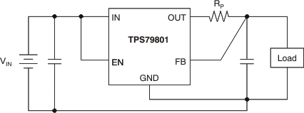
The device is protected against both reverse-input and reverse-output voltages. In battery-backup applications, where the output can be held up by a backup battery when the input is pulled to ground, the TPS798-Q1 acts as if a diode is in series with the device output and prevents reverse current flow. Figure 6-1 and Figure 6-2 illustrate two typical applications.

GUID-33BFAED6-5895-4B9D-B9B0-9E71B1BAFF77-low.gif
ILED = 1.275V / RSET –48V can vary from –4V to –50V.
Figure 6-1 Constant Brightness for Indicator LED Over Wide Input Voltage Range
GUID-EFEBDEB9-BBAB-4725-9755-DAD0D584BB86-low.gifFigure 6-2 Kelvin Sense Connection