SLVSBL0F December 2012 – December 2017 TPS7A66-Q1 , TPS7A69-Q1
PRODUCTION DATA.
- 1 Features
- 2 Applications
- 3 Description
- 4 Revision History
- 5 Pin Configuration and Functions
- 6 Specifications
- 7 Detailed Description
- 8 Application and Implementation
- 9 Power Supply Recommendations
- 10Layout
- 11Device and Documentation Support
- 12Mechanical, Packaging, and Orderable Information
Package Options
Mechanical Data (Package|Pins)
- DGN|8
Thermal pad, mechanical data (Package|Pins)
- DGN|8
Orderable Information
5 Pin Configuration and Functions
D Package (TPS7A69-Q1)
8-Pin SOIC
Top View

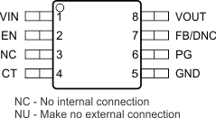
DGN Package (TPS7A66-Q1)
8-Pin HVSSOP
Top View

Pin Functions
| PIN NAME | PIN NO. | TYPE | DESCRIPTION | |
|---|---|---|---|---|
| SOIC-D | HVSSOP-DGN | |||
| CT | 4 | 4 | O | Reset-pulse delay adjustment. Connecting a capacitor from this pin to GND changes the PG reset delay; see the Reset Delay Timer (CT) section for more details. |
| EN | — | 2 | I | Enable pin. The device enters the standby state when the enable pin becomes lower than the enable threshold. |
| FB/DNC | — | 7 | I | Feedback pin when using external resistor divider or DNC pin when using the device with a fixed output voltage. |
| GND | 5 | 5 | G | Ground reference |
| NC | 3 | 3 | — | Not-connected pin |
| PG | 6 | 6 | O | Power good. This open-drain pin must connect to VOUT via an external resistor. VPG is logic level high when VOUT is above the power-on-reset threshold. |
| SI | 2 | I | Sense input pin to supervise input voltage. Connect via an external voltage divider to VIN and GND. | |
| SO | 7 | O | Sense output. This open-drain pin must connect to VOUT via an external resistor. VSO is logic level low when VSI falls below the sense-low threshold. | |
| VIN | 1 | 1 | P | Input power-supply voltage |
| VOUT | 8 | 8 | O | Regulated output voltage |
| Thermal pad | Pad | — | — | Thermal pad for HVSSOP-DGN package |