SBVS189G March 2012 – October 2023 TPS7A7100
PRODUCTION DATA
- 1
- 1 Features
- 2 Applications
- 3 Description
- 4 Pin Configurations
- 5 Specifications
- 6 Detailed Description
- 7 Application and Implementation
- 8 Device And Documentation Support
- 9 Revision History
- 10Mechanical, Packaging, And Orderable Information
Package Options
Refer to the PDF data sheet for device specific package drawings
Mechanical Data (Package|Pins)
- RGT|16
- RGW|20
Thermal pad, mechanical data (Package|Pins)
- RGT|16
Orderable Information
3 Description
The TPS7A7100 low-dropout (LDO) voltage regulator is designed for applications requiring very-low dropout capability (140 mV at 1 A) with an input voltage from 1.5 V to 6.5 V. The TPS7A7100 offers an innovative, user-configurable, output-voltage setting from 0.9 V to 3.5 V, thus eliminating external resistors and any associated errors.
The TPS7A7100 has very fast load-transient response, is stable with ceramic output capacitors, and supports a better than 2% accuracy over line, load, and temperature. A soft-start pin allows for an application to reduce inrush into the load. Additionally, an open-drain, power-good signal allows for sequencing power rails.
The TPS7A7100 is available in 3-mm × 3-mm, 16-pin VQFN and 5-mm × 5-mm, 20-pin VQFN packages.
| PART NUMBER | PACKAGE(1) | PACKAGE SIZE(2) |
|---|---|---|
| TPS7A7100 | RGT (VQFN, 16) | 3 mm × 3 mm |
| RGW (VQFN, 20) | 5 mm × 5 mm |
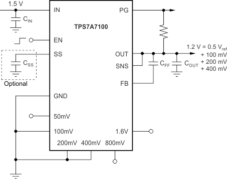
 Typical Application
Circuit
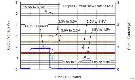
 Load Transient Response With
Seven Different Outputs: 1.5 VIN to 1 VOUT, 1.5
VIN to 1.2 VOUT, 1.8 VIN to 1.5
VOUT, 2.5 VIN to 1.8 VOUT, 3
VIN to 2.5 VOUT, 3.3 VIN to 3
VOUT, and 5.5 VIN to 5 VOUT