-
TPS7H1210-SEP –16.5-V, 1-A, Negative Linear Regulator in Space Enhanced Plastic
- 1 Features
- 2 Applications
- 3 Description
- 4 Revision History
- 5 Pin Configuration and Functions
- 6 Specifications
- 7 Detailed Description
- 8 Application and Implementation
- 9 Power Supply Recommendations
- 10Layout
- 11Device and Documentation Support
- 12Mechanical, Packaging, and Orderable Information
- IMPORTANT NOTICE
Package Options
Mechanical Data (Package|Pins)
- RGW|20
Thermal pad, mechanical data (Package|Pins)
- RGW|20
Orderable Information
TPS7H1210-SEP –16.5-V, 1-A, Negative Linear Regulator in Space Enhanced Plastic
1 Features
- Vendor item drawing available, VID V62/21616
- Total
ionizing dose (TID) characterized to 30 krad(Si)
- TID RLAT (radiation lot acceptance testing) for every wafer lot to 20 krad(Si)
- Single-event
effects (SEE) characterized
- Single-event latchup (SEL), single-event burnout (SEB), and single-event gate rupture (SEGR) immune to linear energy transfer (LET) = 43 MeV-cm2/mg
- Single-event functional interrupt (SEFI) and single-event transient (SET) characterized to LET = 43 MeV-cm2/mg
- Low noise: 13.7-μVRMS typical (10 Hz to 100 kHz)
- High power-supply rejection ration, PSRR (typical
at VIN = –6 V, VOUT = –5 V, IOUT = 1 A):
- 61 dB at 100 Hz
- 61 dB at 100 kHz
- 41 dB at 1 MHz
- Input voltage range: –3 V to –16.5 V
- Adjustable output: –1.2 V to –15.5 V
- Up to 1-A output current
- Stable with ceramic capacitors ≥ 10 μF
- Built-in current-limit and thermal shutdown protection
- Space Enhanced Plastic (SEP)
- Controlled baseline
- Gold bondwire
- NiPdAu lead finish
- One assembly and test site
- One fabrication site
- Military (–55°C to 125°C) temperature range
- Extended product life cycle
- Extended product-change notification (PCN)
- Product traceability
- Enhanced mold compound for low outgassing
2 Applications
- Supports low Earth orbit (LEO) space applications
- Satellite electrical power system (EPS)
- Power for analog circuits
- Data converters: ADCs and DACs (analog-to-digital and digital-to-analog converters)
- Op amps (operational amplifiers)
- Imaging sensors
- Post DC-DC converter regulation and ripple filtering
- Radiation-hardened ultra-clean analog supply for space constrained areas
3 Description
The TPS7H1210-SEP negative voltage linear regulator is a low noise, high PSRR regulator capable of sourcing a maximum load of 1 A.
The regulator include a CMOS logic-level-compatible enable pin (EN) to allow for user-customizable power management schemes. Other features include built-in current limit and thermal shutdown to protect the device and system during fault conditions.
The TPS7H1210-SEP device is designed using bipolar technology primarily for high-accuracy, low-noise applications, where clean voltage rails are critical to maximize system performance. Therefore, it ideal to power op amps, ADCs, DACs, and other high-performance analog circuitry.
Additionally, the TPS7H1210-SEP device is suitable for post DC-DC converter regulation. By filtering the output voltage ripple inherent to DC-DC switching conversion, maximum system performance is ensured in sensitive devices and RF applications.
| PART NUMBER(1) | GRADE | PACKAGE(2) |
|---|---|---|
| TPS7H1210MRGWSEP | 20 krad(Si) RLAT, 30 krad(Si) characterized | VQFN (20) 5.00 mm × 5.00 mm Mass = 83.6 mg |
| TPS7H1210EVM | Evaluation board | EVM |
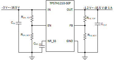
 Typical Application
Schematic
Typical Application
Schematic4 Revision History
| DATE | REVISION | NOTES |
|---|---|---|
| * | Initial Release |
5 Pin Configuration and Functions
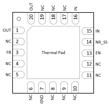
 Figure 5-1 RGW Package,20-Pin VQFN(Top View)
| PIN | I/O(1) | DESCRIPTION | |
|---|---|---|---|
| NAME | NO. | ||
| EN | 13 | I | Enable. This dual-polarity pin turns the regulator on when |VEN| ≥ 2 V. The EN pin can be connected to IN if not used. If VEN is negative polarity, then keep |VEN| ≤ |VIN|. |
| FB | 3 | I | Feedback. This pin is the input to the control-loop error amplifier. It is used to set the output voltage of the device and is normally equal to VREF (–1.182 V, typical) during operation. |
| GND | 7 | — | Ground. |
| IN | 15, 16 | I | Input supply. It is recommended to connect a 10-µF capacitor from IN to GND (as close to the device as possible). |
| NC | 2, 4–6, 8–12, 17–19 | — | No connect. This pin is not internally connected. It is recommended to connect these pins to GND to prevent charge buildup; however, these pins can also be left open or tied to any voltage between GND and VIN. |
| NR_SS | 14 | — | Noise reduction and soft start. A capacitor connected from this pin to GND controls the soft-start function and allows RMS noise to be reduced to very low levels. TI recommends connecting a 100-nF capacitor from NR_SS to GND (as close to the device as possible) to filter the noise generated by the internal band gap and maximize AC performance. |
| OUT | 1, 20 | O | Output of the regulator. A capacitor greater than or equal to 10 µF must be tied from this pin to ground to ensure stability. TI recommends connecting a 47-µF ceramic capacitor from OUT to GND (as close to the device as possible) to maximize AC performance. |
| Thermal Pad |
— | — | Connect the thermal pad to a large-area ground plane. The thermal pad is not internally grounded and it must be externally tied to GND for proper operation. |
6 Specifications
6.1 Absolute Maximum Ratings
| MIN | MAX | UNIT | ||
|---|---|---|---|---|
| Input voltage | IN to GND | –35 | 0.3 | V |
| FB to GND | –2 | 0.3 | V | |
| FB to IN | –0.3 | 35 | V | |
| EN to GND | –35 | 10 | V | |
| NR_SS to IN | –0.3 | 35 | V | |
| NR_SS to GND | –2 | 0.3 | V | |
| Output voltage | OUT to GND | –33 | 0.3 | V |
| OUT to IN | –0.3 | 35 | V | |
| Output current | Peak output | Internally limited | ||
| Operating virtual junction temperature | TJ | –55 | 150 | °C |
| Storage temperature | Tstg | –65 | 150 | °C |