SLLS814A July 2007 – June 2015 TRS3221
PRODUCTION DATA.
- 1 Features
- 2 Applications
- 3 Description
- 4 Revision History
- 5 Pin Configuration and Functions
-
6 Specifications
- 6.1 Absolute Maximum Ratings
- 6.2 ESD Ratings
- 6.3 Recommended Operating Conditions
- 6.4 Thermal Information
- 6.5 Electrical Characteristics—Power
- 6.6 Electrical Characteristics—Driver
- 6.7 Electrical Characteristics—Receiver
- 6.8 Electrical Characteristics—Status
- 6.9 Switching Characteristics—Driver
- 6.10 Switching Characteristics—Receiver
- 6.11 Switching Characteristics—Status
- 6.12 Typical Characteristics
- 7 Parameter Measurement Information
- 8 Detailed Description
- 9 Application and Implementation
- 10Power Supply Recommendations
- 11Layout
- 12Device and Documentation Support
- 13Mechanical, Packaging, and Orderable Information
Package Options
Mechanical Data (Package|Pins)
Thermal pad, mechanical data (Package|Pins)
Orderable Information
7 Parameter Measurement Information

A. CL includes probe and jig capacitance.
B. The pulse generator has the following characteristics: PRR = 250 kbps, ZO = 50 Ω, 50% duty cycle, tr ≤ 10 ns,
tf ≤ 10 ns.
Figure 3. Driver Slew Rate
tf ≤ 10 ns.

A. CL includes probe and jig capacitance.
B. The pulse generator has the following characteristics: PRR = 250 kbps, ZO = 50 Ω, 50% duty cycle, tr ≤ 10 ns,
tf ≤ 10 ns.
Figure 4. Driver Pulse Skew
tf ≤ 10 ns.

A. CL includes probe and jig capacitance.
B. The pulse generator has the following characteristics: ZO = 50 Ω, 50% duty cycle, tr ≤ 10 ns, tf ≤ 10 ns.
Figure 5. Receiver Propagation Delay Times

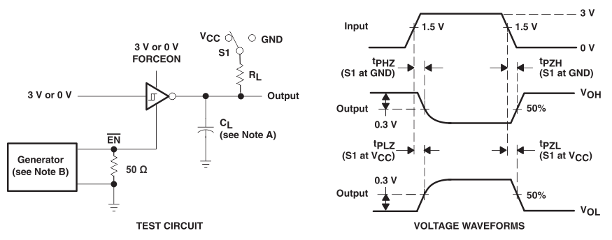
A. CL includes probe and jig capacitance.
B. The pulse generator has the following characteristics: ZO = 50 Ω, 50% duty cycle, tr ≤ 10 ns, tf ≤ 10 ns.
C. tPLZ and tPHZ are the same as tdis.
D. tPZL and tPZH are the same as ten.
Figure 6. Receiver Enable and Disable Times

A. Automatic Power Down disables drivers and reduces supply current to 1 µA.
B. CL includes probe abnd jig capacitance.
C. The pulse generator has the following characteristics: PRR = 5 kbps, ZO = 50 Ω, 50% duty cycle, tr ≤ 10 ns, tf ≤ 10 ns.
Figure 7. INVALID Propagation Delay Times and Driver Enabling Time