SCDS328C October 2011 – August 2015 TS3USBA225
PRODUCTION DATA.
- 1 Features
- 2 Applications
- 3 Description
- 4 Revision History
- 5 Pin Configuration and Functions
- 6 Specifications
- 7 Detailed Description
- 8 Application and Implementation
- 9 Power Supply Recommendations
- 10Layout
- 11Device and Documentation Support
- 12Mechanical, Packaging, and Orderable Information
Package Options
Mechanical Data (Package|Pins)
- RUT|12
Thermal pad, mechanical data (Package|Pins)
Orderable Information
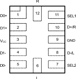
5 Pin Configuration and Functions
RUT Package
12-Pin UQFN
Top View

Pin Functions
| PIN | I/O | DESCRIPTION | |
|---|---|---|---|
| NAME | NO. | ||
| D0+ | 1 | I/O | MHL/USB/UART Data 1 (Differential +) |
| D1+ | 2 | I/O | MHL/USB/UART Data 2 (Differential +) |
| VCC | 3 | - | Power supply |
| D1– | 4 | I/O | MHL/USB/UART Data 2 (Differential –) |
| D0– | 5 | I/O | MHL/USB/UART Data 1 (Differential –) |
| L | 6 | I/O | USB-/Left Channel Audio |
| SEL2 | 7 | I | Control Input Select Line 2. The default state for SEL2 is LOW. |
| D–/L | 8 | I/O | MHL/USB/UART/Audio Common Connector |
| GND | 9 | - | Ground |
| D+/R | 10 | I/O | MHL/USB/UART/Audio Common Connector |
| SEL1 | 11 | I | Control Input Select Line 1. The default state for SEL1 is LOW. |
| R | 12 | I/O | USB+/Right Channel Audio |