-
TS5A3159-Q1 1-Ω SPDT Analog Switch
- 1 Features
- 2 Applications
- 3 Description
- 4 Revision History
- 5 Pin Configuration and Functions
-
6 Specifications
- 6.1 Absolute Maximum Ratings
- 6.2 ESD Ratings
- 6.3 Recommended Operating Conditions
- 6.4 Thermal Information
- 6.5 Electrical Characteristics for 5-V Supply
- 6.6 Electrical Characteristics for 3.3-V Supply
- 6.7 Electrical Characteristics For 2.5-V Supply
- 6.8 Electrical Characteristics For 1.8-V Supply
- 6.9 Typical Characteristics
- 7 Parameter Measurement Information
- 8 Detailed Description
- 9 Applications and Implementation
- 10Power Supply Recommendations
- 11Layout
- 12Device and Documentation Support
- 13Mechanical, Packaging, and Orderable Information
- IMPORTANT NOTICE
Package Options
Refer to the PDF data sheet for device specific package drawings
Mechanical Data (Package|Pins)
- DBV|6
Thermal pad, mechanical data (Package|Pins)
Orderable Information
TS5A3159-Q1 1-Ω SPDT Analog Switch
1 Features
- Qualified for Automotive Applications
- AEC-Q100 Qualified with the Following Results:
- Device Temperature Grade 1: –40°C to +125°C Ambient Operating Temperature Range
- Device HBM ESD Classification Level 2
- Device CDM ESD Classification Level C4B
- Specified Break-Before-Make Switching
- Low ON-State Resistance (1 Ω)
- Control Inputs are 5-V Tolerant
- Low Charge Injection
- Excellent ON-Resistance Matching
- Low Total Harmonic Distortion
- 1.65-V to 5.5-V Single-Supply Operation
2 Applications
- Automotive Infotainment and Cluster
- Body Electronics and Lighting
3 Description
The TS5A3159-Q1 is a single-pole double-throw (SPDT) analog switch that is designed to operate from 1.65 V to 5.5 V. The device offers a low ON-state resistance and an excellent ON-resistance, matching with the break-before-make feature to prevent signal distortion during the transferring of a signal from one channel to another. The device has an excellent total harmonic distortion (THD) performance and consumes very low power. These features make this device suitable for portable audio applications.
Device Information(1)
| PART NUMBER | PACKAGE | BODY SIZE (NOM) |
|---|---|---|
| TS5A3159-Q1 | SOT-23 (6) | 2.90 mm × 4.00 mm |
- For all available packages, see the orderable addendum at the end of the datasheet.
Selector Application

4 Revision History
Changes from B Revision (October 2015) to C Revision
- Changed I/O for V+ from I to —Go
- Added VNC to Analog voltage, Analog port diode current, and ON−state switch currentGo
- Added Junction temperature, TJ to Absolute Maximum RatingsGo
- Changed MIN value for V+ from 1.8 to 1.65 and MAX value from 5 to 5.5Go
- Changed MAX value for IN from 5 to 5.5Go
- Changed MAX value for NO, NC, COM from 5 to V+Go
- Added VIL MAX value 0.6 and deleted TYP value 0.6Go
- Added Receiving Notification of Documentation Updates section Go
Changes from A Revision (December 2012) to B Revision
- Added ESD Ratings table, Feature Description section, Device Functional Modes, Application and Implementation section, Power Supply Recommendations section, Layout section, Device and Documentation Support section, and Mechanical, Packaging, and Orderable Information section Go
Changes from * Revision (November, 2012) to A Revision
- Device going from Preview to ProductionGo
- Changed ron max values from 1.1 to 1.3Go
- Changed INC(OFF), INO(OFF) min and max values for 25°C from –2 and 2 to –6 and 6, respectively. Changed min and max values for Full from –20 and 20 to –150 and 150, respectively.Go
- Changed INC(ON), INO(ON) min and max values for 25°C from –4 and 4 to –6 and 6, respectively. Changed min and max values for Full from –40 and 40 to –150 and 150, respectively.Go
- Changed ICOM(ON) min and max values for 25°C from –4 and 4 to –8 and 8, respectively. Changed min and max values for Full from –40 and 40 to –150 and 150, respectively. Go
- Inserted 25°C above Full in TA column and inserted 0.5 µA max value for I+Go
- Changed max values for rpeak from 2.1 to 2.2.Go
- Changed max values for ron from 1.5 to 1.8.Go
- Added 25°C to TA column and added 0.5 max value to I+Go
- Changed rpeak max values from 2.7 to 2.9.Go
- Changed ron max values from 2 to 2.3.Go
- Added 25°C to TA column and added 0.5 max value to I+.Go
- Changed rpeak max values from 4.9 to 5.2.Go
- Changed ron max values from 3.2 to 3.5.Go
- Added 25°C to TA column and added 0.5 max value to I+.Go
- Changed ON-state resistance from 1.1 to 1.3 Ω.Go
- Changd leakage current from ±20 nA to ±6 nA.Go
5 Pin Configuration and Functions

6 Specifications
6.1 Absolute Maximum Ratings
over operating free-air temperature range (unless otherwise noted) (1)| MIN | MAX | UNIT | |||
|---|---|---|---|---|---|
| V+ | Supply voltage(2) | –0.5 | 6.5 | V | |
| VNO, VNC, VCOM | Analog voltage(2)(3)(4) | –0.5 | V+ + 0.5 | V | |
| II/OK | Analog port diode current | VNO, VNC, VCOM < 0 or VNO, VNC, VCOM > V+ | ±50 | mA | |
| INO, INC, ICOM | ON−state switch current | VNO, VNC, VCOM = 0 to V+ | ±200 | mA | |
| ON−state peak switch current(5) | ±400 | mA | |||
| VIN | Digital input voltage range(2)(3) | –0.5 | 6.5 | V | |
| IIK | Digital input clamp current | VIN < 0 | −50 | mA | |
| Continuous current through V+ or GND | ±100 | mA | |||
| TJ | Junction temperature | 150 | °C | ||
| Tstg | Storage temperature | –65 | 150 | °C | |
6.2 ESD Ratings
| VALUE | UNIT | ||||
|---|---|---|---|---|---|
| V(ESD) | Electrostatic discharge | Human body model (HBM), per AEC Q100-002(1) | ±2000 | V | |
| Charged device model (CDM), per AEC Q100-011 | Corner pins (NO, NC, IN, and COM) | ±750 | |||
| Other pins | ±500 | ||||
6.3 Recommended Operating Conditions
over operating free-air temperature range (unless otherwise noted)| MIN | MAX | UNIT | ||
|---|---|---|---|---|
| V+ | 1.65 | 5.5 | V | |
| IN | 0 | 5.5 | V | |
| NO, NC, COM | 0 | V+ | V | |
6.4 Thermal Information
| THERMAL METRIC(1) | TS5A3159-Q1 | UNIT | |
|---|---|---|---|
| DBV (SOT-23) | |||
| 6 PINS | |||
| RθJA | Junction-to-ambient thermal resistance | 192.9 | °C/W |
| RθJC(top) | Junction-to-case (top) thermal resistance | 133.3 | °C/W |
| RθJB | Junction-to-board thermal resistance | 37.6 | °C/W |
| ψJT | Junction-to-top characterization parameter | 38.9 | °C/W |
| ψJB | Junction-to-board characterization parameter | 37.1 | °C/W |
| RθJC(bot) | Junction-to-case (bottom) thermal resistance | N/A | °C/W |
6.5 Electrical Characteristics for 5-V Supply
V+ = 4.5 V to 5.5 V and TA = −40°C to +125°C (unless otherwise noted)| PARAMETER | TEST CONDITIONS | TA | V+ | MIN | TYP(1) | MAX | UNIT | ||
|---|---|---|---|---|---|---|---|---|---|
| ANALOG SWITCH | |||||||||
| VCOM, VNO,VNC | Analog signal range | 0 | V+ | V | |||||
| rpeak | Peak ON resistance | 0 ≤ VNO or VNC ≤ V+, ICOM = –30 mA |
Switch ON, See Figure 11 |
25°C | 4.5 V | 1 | 1.5 | Ω | |
| Full | 1.5 | ||||||||
| ron | ON-state resistance | VNO or VNC = 2.5 V, ICOM = –30 mA |
Switch ON, See Figure 10 |
25°C | 4.5 V | 0.75 | 1.3 | Ω | |
| Full | 1.3 | ||||||||
| ∆ron | ON-state resistance match between channels | VNO or VNC = 2.5 V, ICOM = –30 mA |
Switch ON, See Figure 10 |
25°C | 4.5 V | 0.1 | Ω | ||
| ron(flat) | ON-state resistance flatness | 0 ≤ VNO or VNC ≤ V+, ICOM = –30 mA |
Switch ON, See Figure 10 |
25°C | 4.5 V | 0.233 | Ω | ||
| VNO or VNC = 1 V, 1.5 V, 2.5 V, ICOM = –30 mA |
25°C | 0.15 | |||||||
| INC(OFF), INO(OFF) | NC, NO OFF leakage current |
VNC or VNO = 4.5 V, VCOM = 0 |
Switch OFF, See Figure 12 |
25°C | 5.5 V | −6 | 0.2 | 6 | nA |
| Full | −150 | 150 | |||||||
| INC(ON), INO(ON) | NC, NO ON leakage current |
VNC or VNO = 4.5 V, VCOM = Open |
Switch ON, See Figure 13 |
25°C | 5.5 V | −6 | 2.8 | 6 | nA |
| Full | −150 | 150 | |||||||
| ICOM(ON) | COM ON leakage current |
VNC or VNO = 4.5 V or Open, VCOM = 4.5 V |
Switch ON, See Figure 13 |
25°C | 5.5 V | –8 | 0.47 | 8 | nA |
| Full | −150 | 150 | |||||||
| DIGITAL INPUTS (IN) | |||||||||
| VIH | Input logic high | Full | 2.4 | 5.5 | V | ||||
| VIL | Input logic low | Full | 0 | 0.8 | V | ||||
| IIH, IIL | Input leakage current | VIN = 5.5 V or 0 | Full | 5.5 V | −1 | 1 | µA | ||
| DYNAMIC | |||||||||
| tON | Turn-on time | VCOM = V+, RL = 50 Ω, |
CL = 35 pF, See Figure 15 |
25°C | 4.5 V to 5.5 V | 20 | 35 | ns | |
| Full | 40 | ||||||||
| tOFF | Turn-off time | VCOM = V+, RL = 50 Ω, |
CL = 35 pF, See Figure 15 |
25°C | 4.5 V to 5.5 V | 15 | 20 | ns | |
| Full | 35 | ||||||||
| tBBM | Break-before-make time | VNC = VNO = V+ / 2, RL = 50 Ω, |
CL = 35 pF, See Figure 16 |
25°C | 4.5 V to 5.5 V | 1 | 12 | 14.5 | ns |
| Full | 1 | ||||||||
| QC | Charge injection | CL = 1 nF, VGEN = 0 V, | See Figure 19 | 25°C | 5 V | 36 | pC | ||
| CNC(OFF), CNO(OFF) | NC, NO OFF capacitance |
VNC or VNO = V+ or GND, Switch OFF, |
See Figure 13 | 25°C | 5 V | 23 | pF | ||
| CNC(ON), CNO(ON) | NC, NO ON capacitance |
VNC or VNO = V+ or GND, Switch ON, |
See Figure 13 | 25°C | 5 V | 84 | pF | ||
| CCOM(ON) | COM ON capacitance |
VCOM = V+ or GND, Switch ON, |
See Figure 13 | 25°C | 5 V | 84 | pF | ||
| CIN | Digital input capacitance | VIN = V+ or GND, | See Figure 13 | 25°C | 5 V | 2.1 | pF | ||
| BW | Bandwidth | RL = 50 Ω, Switch ON, |
See Figure 16 | 25°C | 5 V | 100 | MHz | ||
| OISO | OFF isolation | RL = 50 Ω, f = 1 MHz, |
Switch OFF, See Figure 17 |
25°C | 5 V | –65 | dB | ||
| XTALK | Crosstalk | RL = 50 Ω, f = 1 MHz, |
Switch ON, See Figure 18 |
25°C | 5 V | –65 | dB | ||
| THD | Total harmonic distortion | RL = 600 Ω, CL = 50 pF, |
f = 600 Hz to 20 kHz, See Figure 19 |
25°C | 5 V | 0.01% | |||
| SUPPLY | |||||||||
| I+ | Positive supply current | VIN = V+ or GND, | Switch ON or OFF | 25°C | 5.5 V | 0.1 | µA | ||
| Full | 0.5 | ||||||||
6.6 Electrical Characteristics for 3.3-V Supply
V+ = 3 V to 3.6 V and TA = −40°C to +125°C (unless otherwise noted)| PARAMETER | TEST CONDITIONS | TA | V+ | MIN | TYP(1) | MAX | UNIT | ||
|---|---|---|---|---|---|---|---|---|---|
| ANALOG SWITCH | |||||||||
| VCOM, VNO,VNC | Analog signal range | 0 | V+ | V | |||||
| rpeak | Peak ON-state resistance | 0 ≤ VNO or VNC ≤ V+, ICOM = –24 mA, |
Switch ON, See Figure 10 |
25°C | 3 V | 1.35 | 2.2 | Ω | |
| Full | 2.2 | ||||||||
| ron | ON-state resistance | VNO or VNC = 2 V, ICOM = –24 mA, |
Switch ON, See Figure 10 |
25°C | 3 V | 1.15 | 1.8 | Ω | |
| Full | 1.8 | ||||||||
| ∆ron | ON-state resistance match between channels | VNO or VNC = 2 V, 0.8 V, ICOM = –24 mA, |
Switch ON, See Figure 10 |
25°C | 3 V | 0.11 | Ω | ||
| ron(flat) | ON-state resistance flatness | 0 ≤ VNO or VNC ≤ V+, ICOM = –24 mA, |
Switch ON, See Figure 10 |
25°C | 3 V | 0.225 | Ω | ||
| VNO or VNC = 2 V, 0.8 V, ICOM = –24 mA, |
25°C | 0.25 | |||||||
| INC(OFF), INO(OFF) |
NC, NO OFF leakage current |
VNC or VNO = 3 V, VCOM = 0, |
Switch OFF, See Figure 11 |
25°C | 3.6 V | 0.2 | nA | ||
| INC(ON), INO(ON) |
NC, NO ON leakage current |
VNC or VNO = 3 V, VCOM = Open, |
Switch ON, See Figure 12 |
25°C | 3.6 V | 2.8 | nA | ||
| ICOM(ON) | COM ON leakage current |
VNC or VNO = 3 V or Open, VCOM = 3 V, |
Switch ON, See Figure 12 |
25°C | 3.6 V | 0.47 | nA | ||
| DIGITAL INPUTS (IN) | |||||||||
| VIH | Input logic high | Full | 2 | 5.5 | V | ||||
| VIL | Input logic low | Full | 0 | 0.6 | V | ||||
| IIH, IIL | Input leakage current | VIN = 5.5 V or 0 | Full | 3.6 V | –1 | 1 | µA | ||
| DYNAMIC | |||||||||
| tON | Turn-on time | VCOM = V+, RL = 50 Ω |
CL = 35 pF, See Figure 15 |
25°C | 3 V to 3.6 V | 30 | 40 | ns | |
| Full | 55 | ||||||||
| tOFF | Turn-off time | VCOM = V+, RL = 50 Ω |
CL = 35 pF, See Figure 15 |
25°C | 3 V to 3.6 V | 20 | 25 | ns | |
| Full | 40 | ||||||||
| tBBM | Break-before-make time | VNC = VNO = V+ / 2, RL = 50 Ω |
CL = 35 pF, See Figure 16 |
25°C | 3 V to 3.6 V | 1 | 21 | 29 | ns |
| Full | 1 | ||||||||
| QC | Charge injection | CL = 1 nF, VGEN = 0 V | See Figure 19 | 25°C | 3.3 V | 20 | pC | ||
| CNC(OFF), CNO(OFF) | NC, NO OFF capacitance | VNC or VNO = V+ or GND, Switch OFF |
See Figure 13 | 25°C | 3.3 V | 23 | pF | ||
| CNC(ON), CNO(ON) | NC, NO ON capacitance | VNC or VNO = V+ or GND, Switch ON |
See Figure 13 | 25°C | 3.3 V | 84 | pF | ||
| CCOM(ON) | COM ON capacitance | VCOM = V+ or GND, Switch ON |
See Figure 13 | 25°C | 3.3 V | 84 | pF | ||
| CIN | Digital input capacitance | VIN = V+ or GND | See Figure 13 | 25°C | 3.3 V | 2.1 | pF | ||
| BW | Bandwidth | RL = 50 Ω, Switch ON |
See Figure 16 | 25°C | 3.3 V | 100 | MHz | ||
| OISO | OFF isolation | RL = 50 Ω, f = 1 MHz |
Switch OFF, See Figure 17 |
25°C | 3.3 V | –65 | dB | ||
| XTALK | Crosstalk | RL = 50 Ω, f = 1 MHz |
Switch ON, See Figure 18 |
25°C | 3.3 V | –65 | dB | ||
| THD | Total harmonic distortion | RL = 600 Ω, CL = 50 pF |
f = 600 Hz to 20 kHz, See Figure 19 |
25°C | 3.3 V | 0.015% | |||
| SUPPLY | |||||||||
| I+ | Positive supply current | VIN = V+ or GND | Switch ON or OFF | 25°C | 3.6 V | 0.1 | μA | ||
| Full | 0.5 | ||||||||
6.7 Electrical Characteristics For 2.5-V Supply
V+ = 2.3 V to 2.7 V and TA = −40°C to +125°C (unless otherwise noted)| PARAMETER | TEST CONDITIONS | TA | V+ | MIN | TYP(1) | MAX | UNIT | ||
|---|---|---|---|---|---|---|---|---|---|
| ANALOG SWITCH | |||||||||
| VCOM, VNO,VNC | Analog signal range | 0 | V+ | V | |||||
| rpeak | Peak ON-state resistance | 0 ≤ VNO or VNC ≤ V+, ICOM = –8 mA |
Switch ON, See Figure 10 |
25°C | 2.5 V | 1.7 | 2.9 | Ω | |
| Full | 2.9 | ||||||||
| ron | ON-state resistance | VNO or VNC = 1.8 V, ICOM = –8 mA |
Switch ON, See Figure 10 |
25°C | 2.5 V | 1.45 | 2.3 | Ω | |
| Full | 2.3 | ||||||||
| ∆ron | ON-state resistance match between channels | VNO or VNC = 0.8 V, 1.8 V, ICOM = –8 mA |
Switch ON, See Figure 10 |
25°C | 2.5 V | 0.7 | Ω | ||
| ron(flat) | ON-state resistance flatness | 0 ≤ VNO or VNC ≤ V+, ICOM = –8 mA |
Switch ON, See Figure 10 |
25°C | 2.5 V | 0.5 | Ω | ||
| VNO or VNC = 0.8 V, 1.8 V, ICOM = –8 mA |
25°C | 0.45 | |||||||
| INC(OFF), INO(OFF) | NC, NO Off leakage current |
VNC or VNO = 2.3 V, VCOM = 0 |
Switch OFF, See Figure 11 |
25°C | 2.7 V | 0.2 | nA | ||
| INC(ON), INO(ON) | NC, NO On leakage current |
VNC or VNO = 2.3 V, VCOM = Open |
Switch ON, See Figure 12 |
25°C | 2.7 V | 2.8 | nA | ||
| ICOM(ON) | COM On leakage current |
VNC or VNO = 2.3 V or Open, VCOM = 2.3 V |
Switch ON, See Figure 12 |
25°C | 2.7 V | 0.47 | nA | ||
| DIGITAL INPUTS (IN) | |||||||||
| VIH | Input logic high | Full | 1.8 | 5.5 | V | ||||
| VIL | Input logic low | Full | 0 | 0.6 | V | ||||
| IIH, IIL | Input leakage current | VIN = 5.5 V or 0 | Full | 2.7 V | −1 | 1 | µA | ||
| DYNAMIC | |||||||||
| tON | Turn-on time | VCOM = V+, RL = 50 Ω, |
CL = 35 pF, See Figure 15 |
25°C | 2.3 V to 2.7 V | 40 | 55 | ns | |
| Full | 70 | ||||||||
| tOFF | Turn-off time | VCOM = V+, RL = 50 Ω, |
CL = 35 pF, See Figure 15 |
25°C | 2.3 V to 2.7 V | 30 | 40 | ns | |
| Full | 55 | ||||||||
| tBBM | Break-before-make time | VNC = VNO = V+ / 2, RL = 50 Ω, |
CL = 35 pF, See Figure 16 |
25°C | 2.3 V to 2.7 V | 1 | 33 | 39 | ns |
| Full | 1 | ||||||||
| QC | Charge injection | CL = 1 nF, VGEN = 0 V, | See Figure 19 | 25°C | 2.5 V | 13 | pC | ||
| CNC(OFF), CNO(OFF) |
NC, NO OFF capacitance |
VNC or VNO = V+ or GND, Switch OFF, |
See Figure 14 | 25°C | 2.5 V | 23 | pF | ||
| CNC(ON), CNO(ON) |
NC, NO ON capacitance |
VNC or VNO = V+ or GND, Switch ON, |
See Figure 14 | 25°C | 2.5 V | 84 | pF | ||
| CCOM(ON) | COM ON capacitance |
VCOM = V+ or GND, Switch ON, |
See Figure 14 | 25°C | 2.5 V | 84 | pF | ||
| CIN | Digital input capacitance | VIN = V+ or GND, | See Figure 14 | 25°C | 2.5 V | 2.1 | pF | ||
| BW | Bandwidth | RL = 50 Ω, Switch ON, |
See Figure 16 | 25°C | 2.5 V | 100 | MHz | ||
| OISO | OFF isolation | RL = 50 Ω, f = 1 MHz, |
Switch OFF, See Figure 17 |
25°C | 2.5 V | –64 | dB | ||
| XTALK | Crosstalk | RL = 50 Ω, f = 1 MHz, |
Switch ON, See Figure 18 |
25°C | 2.5 V | –64 | dB | ||
| THD | Total harmonic distortion | RL = 600 Ω, CL = 50 pF, |
f = 600 Hz to 20 kHz, See Figure 19 |
25°C | 2.5 V | 0.025% | |||
| SUPPLY | |||||||||
| I+ | Positive supply current | VIN = V+ or GND, | Switch ON or OFF | 25°C | 2.7 V | 0.1 | μA | ||
| Full | 0.5 | ||||||||
6.8 Electrical Characteristics For 1.8-V Supply
V+ = 1.65 V to 1.95 V and TA = −40°C to +125°C (unless otherwise noted| PARAMETER | TEST CONDITIONS | TA | V+ | MIN | TYP(1) | MAX | UNIT | ||
|---|---|---|---|---|---|---|---|---|---|
| ANALOG SWITCH | |||||||||
| VCOM, VNO,VNC | Analog signal range | 0 | V+ | V | |||||
| rpeak | Peak ON-state resistance |
0 ≤ VNO or VNC ≤ V+, ICOM = −2 mA |
Switch ON, See Figure 10 |
25°C | 1.8 V | 4 | 5.2 | Ω | |
| Full | 5.2 | ||||||||
| ron | ON-state resistance | VNO or VNC = 1.5 V, ICOM = −2 mA |
Switch ON, See Figure 10 |
25°C | 1.8 V | 1.7 | 3.5 | Ω | |
| Full | 3.5 | ||||||||
| ∆ron | ON-state resistance match between channels | VNO or VNC = 0.6 V, 1.5 V, ICOM = −2 mA |
Switch ON, See Figure 10 |
25°C | 1.8 V | 0.7 | Ω | ||
| Full | 0.7 | ||||||||
| ron(flat) | ON-state resistance flatness | 0 ≤ VNO or VNC ≤ V+, ICOM = −2 mA |
Switch ON, See Figure 11 |
25°C | 1.8 V | 1.85 | Ω | ||
| Full | 1.85 | ||||||||
| VNO or VNC = 0.6 V, 1.5 V, ICOM = −2 mA |
25°C | 0.9 | |||||||
| Full | 0.9 | ||||||||
| INC(OFF), INO(OFF) | NC, NO Off leakage current |
VNC or VNO = 1.65 V, VCOM = 0 |
Switch OFF, See Figure 11 |
25°C | 1.95 V | 0.2 | nA | ||
| INC(ON), INO(ON) | NC, NO On leakage current |
VNC or VNO = 1.65 V, VCOM = Open |
Switch ON, See Figure 12 |
25°C | 1.95 V | 2.8 | nA | ||
| ICOM(ON) | COM On leakage current |
VNC or VNO = 1.65 V or Open, VCOM = 1.65 V |
Switch ON, See Figure 12 |
25°C | 1.95 V | 0.47 | nA | ||
| DIGITAL INPUTS (IN) | |||||||||
| VIH | Input logic high | Full | 1.5 | 5.5 | V | ||||
| VIL | Input logic low | Full | 0 | 0.6 | V | ||||
| IIH, IIL | Input leakage current | VIN = 5.5 V or 0 | Full | 1.95 V | −1 | 1 | µA | ||
| DYNAMIC | |||||||||
| tON | Turn-on time | VCOM = V+, RL = 50 Ω, |
CL = 35 pF, See Figure 15 |
25°C | 1.65 V to 1.95 V | 65 | 70 | ns | |
| Full | 95 | ||||||||
| tOFF | Turn-off time | VCOM = V+, RL = 50 Ω, |
CL = 35 pF, See Figure 15 |
25°C | 1.65 V to 1.95 V | 40 | 55 | ns | |
| Full | 70 | ||||||||
| tBBM | Break-before-make time | VNC = VNO = V+ / 2, RL = 50 Ω, |
CL = 35 pF, See Figure 15 |
25°C | 1.65 V to 1.95 V | 1 | 60 | 72 | ns |
| Full | 0.5 | ||||||||
| QC | Charge injection | CL = 1 nF, VGEN = 0 V, | See Figure 19 | 25°C | 1.8 V | 13 | pC | ||
| CNC(OFF), CNO(OFF) |
NC, NO OFF capacitance |
VNC or VNO = V+ or GND, Switch OFF, |
See Figure 14 | 25°C | 1.8 V | 23 | pF | ||
| CNC(ON), CNO(ON) |
NC, NO ON capacitance |
VNC or VNO = V+ or GND, Switch ON, |
See Figure 14 | 25°C | 1.8 V | 84 | pF | ||
| CCOM(ON) | COM ON capacitance |
VCOM = V+ or GND, Switch ON, |
See Figure 14 | 25°C | 1.8 V | 84 | pF | ||
| CIN | Digital input capacitance | VIN = V+ or GND, | See Figure 14 | 25°C | 1.8 V | 2.1 | pF | ||
| BW | Bandwidth | RL = 50 Ω, Switch ON, |
See Figure 16 | 25°C | 1.8 V | 100 | MHz | ||
| OISO | OFF isolation | RL = 50 Ω, f = 1 MHz, |
Switch OFF, See Figure 17 |
25°C | 1.8 V | –63 | dB | ||
| XTALK | Crosstalk | RL = 50 Ω, f = 1 MHz, |
Switch ON, See Figure 18 |
25°C | 1.8 V | –63 | dB | ||
| SUPPLY | |||||||||
| I+ | Positive supply current | VIN = V+ or GND, | Switch ON or OFF | 25°C | 1.95 V | 0.1 | μA | ||
| Full | 0.5 | ||||||||
6.9 Typical Characteristics
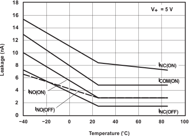
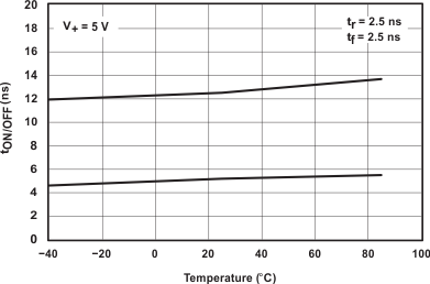
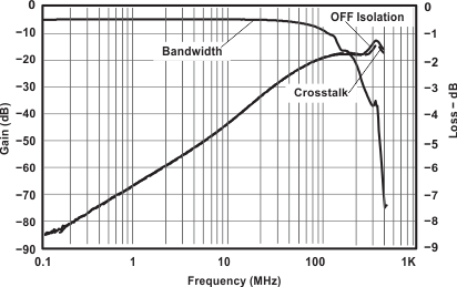
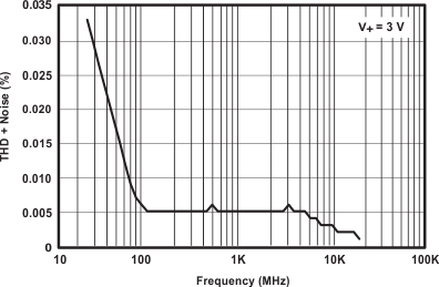
7 Parameter Measurement Information
Table 1. Parameter Description
| SYMBOL | DESCRIPTION |
|---|---|
| VCOM | Voltage at COM |
| VNC | Voltage at NC |
| VNO | Voltage at NO |
| ron | Resistance between COM and NC or COM and NO ports, when the channel is ON |
| rpeak | Peak ON-state resistance over a specified voltage range |
| ∆ron | Difference of ron between channels |
| ron(flat) | Difference between the maximum and minimum value of ron in a channel over the specified range of conditions |
| INC(OFF) | Leakage current measured at the NC port, with the corresponding channel (NC to COM) in the OFF state under worst-case input and output conditions |
| INO(OFF) | Leakage current measured at the NO port, with the corresponding channel (NO to COM) in the OFF state under worst-case input and output conditions |
| INC(ON) | Leakage current measured at the NC port, with the corresponding channel (NC to COM) in the ON state and the output (COM) being open |
| INO(ON) | Leakage current measured at the NO port, with the corresponding channel (NO to COM) in the ON state and the output (COM) being open |
| ICOM(ON) | Leakage current measured at the COM port, with the corresponding channel (COM to NO or COM to NC) in the ON state and the output (NC or NO) being open |
| VIH | Minimum input voltage for logic high for the control input (IN) |
| VIL | Minimum input voltage for logic low for the control input (IN) |
| VIN | Voltage at IN |
| IIH, IIL | Leakage current measured at IN |
| tON | Turn-on time for the switch. This parameter is measured under the specified range of conditions and by the propagation delay between the digital control (IN) signal and analog outputs (COM, NC, or NO) signal, when the switch is turning ON. |
| tOFF | Turn-off time for the switch. This parameter is measured under the specified range of conditions and by the propagation delay between the digital control (IN) signal and analog outputs (COM, NC, or NO) signal, when the switch is turning OFF. |
| tBBM | Break-before-make time. This parameter is measured under the specified range of conditions and by the propagation delay between the output of two adjacent analog channels (NC and NO), when the control signal changes state. |
| QC | Charge injection is a measurement of unwanted signal coupling from the control (IN) input to the analog (NC, NO, or COM) output. This is measured in coulomb (C) and measured by the total charge induced due to switching of the control input. Charge injection, QC = CL × ∆VO, CL is the load capacitance, and ∆VO is the change in analog output voltage. |
| CNC(OFF) | Capacitance at the NC port when the corresponding channel (NC to COM) is OFF |
| CNO(OFF) | Capacitance at the NO port when the corresponding channel (NO to COM) is OFF |
| CNC(ON) | Capacitance at the NC port when the corresponding channel (NC to COM) is ON |
| CNO(ON) | Capacitance at the NO port when the corresponding channel (NO to COM) is ON |
| CCOM(ON) | Capacitance at the COM port when the corresponding channel (COM to NC or COM to NO) is ON |
| CIN | Capacitance of IN |
| OISO | OFF isolation of the switch is a measurement OFF-state switch impedance. This is measured in dB in a specific frequency, with the corresponding channel (NC to COM or NO to COM) in the OFF state. |
| XTALK | Crosstalk is a measurement of unwanted signal coupling from an ON channel to an OFF channel (NC to NO or NO to NC). This is measured in a specific frequency and in dB. |
| BW | Bandwidth of the switch. This is the frequency in which the gain of an ON channel is −3 dB below the DC gain. |
| I+ | Static power-supply current with the control (IN) pin at V+ or GND |
| ∆I+ | This is the increase in I+ for each control (IN) input that is at the specified voltage, rather than at V+ or GND. |
 Figure 9. On-State Resistance (ron)
 Figure 10. Off-State Leakage Current (INC(OFF), INO(OFF))
 Figure 11. On-State Leakage Current (ICOM(ON), INC(ON), INO(ON))
 Figure 12. Capacitance (CI, CCOM(ON), CNC(OFF), CNO(OFF), CNC(ON), CNO(ON))
 Figure 13. Turn-On (tON) and Turn-Off Time (tOFF)
 Figure 14. Break-Before-Make Time (tBBM)
 Figure 15. Bandwidth (BW)
 Figure 16. OFF Isolation (OISO)
 Figure 17. Crosstalk (XTALK)
 Figure 18. Charge Injection (QC)
 Figure 19. Total Harmonic Distortion (THD)
8 Detailed Description
8.1 Overview
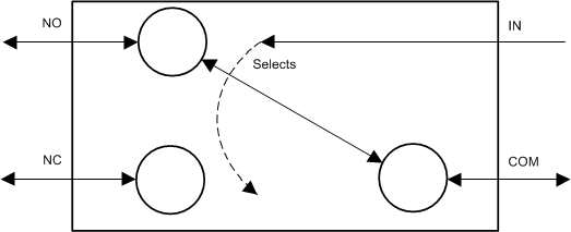
The TS5A3159-Q1 is a single-pole double-throw (SPDT) analog switch designed to operate from 1.65 V to 5.5 V. Either the NO or the NC pin is shorted to the COM pin, depending on the logic level input to the IN pin.
8.2 Functional Block Diagram
8.3 Feature Description
The main feature of this device is the excellent total harmonic distortion performance and low power consumption. Additionally, the NO, NC, and COM pins can be used as either inputs or outputs.
Table 2. Summary Of Characteristics(1)
8.4 Device Functional Modes
Table 3 lists the functions for the TS5A3159-Q1 device.
Table 3. Function Table
| IN | NC TO COM, COM TO NC |
NO TO COM, COM TO NO |
|---|---|---|
| L | ON | OFF |
| H | OFF | ON |
9 Applications and Implementation
NOTE
Information in the following applications sections is not part of the TI component specification, and TI does not warrant its accuracy or completeness. TI’s customers are responsible for determining suitability of components for their purposes. Customers should validate and test their design implementation to confirm system functionality.
9.1 Application Information
Analog switches are commonly used in battery powered applications to route audio signals. A typical use case is highlighted in Figure 20. The analog switch is supplied with 5 V and the control input is from a 5-V processor GPIO. In this case, there are no concerns related to excess power consumption.
9.2 Typical Application
 Figure 20. Typical Application Schematic
9.2.1 Design Requirements
In this application example, the device receives the control signal from a 5-V GPIO and common input from an Audio Power amplifier. The input is routed to either the Hands free set or the internal speaker depending upon the control signal.
9.2.2 Detailed Design Procedure
Since the control signal varies from 0 to 5 V (Vdd), there’s no excess current consumption. However, if the control signal comes from lower voltage GPIOs while the V+ of TS5A3159 is connected to the battery whose voltage varies, it can lead to an excess current draw from the V+ suppl pin. Such a scenario requires the use of an external voltage level translator such as the SN74LVC1T45. For more information see Preventing Excess Current Consumption on Analog Switches, SCDA011.
9.2.3 Application Curve
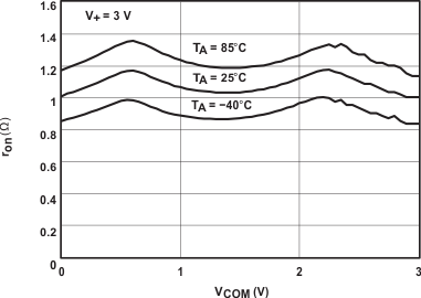
The ON state resistance of the switch is a critical parameter to measure since it helps select the right switch for the application. The on state resistance versus the common voltage can be seen in Figure 21.
