SLVSHX0 October 2024 TSD12C-Q1 , TSD15C-Q1 , TSD18C-Q1 , TSD24C-Q1 , TSD36C-Q1
PRODUCTION DATA
- 1
- 1 Features
- 2 Applications
- 3 Description
- 4 Pin Configuration and Functions
-
5 Specifications
- 5.1 Absolute Maximum Ratings
- 5.2 ESD Ratings - AEC Specifications
- 5.3 ESD Ratings—IEC Specification
- 5.4 ESD Ratings - ISO Specifications
- 5.5 Recommended Operating Conditions
- 5.6 Thermal Information
- 5.7 Electrical Characteristics - TSD12C-Q1
- 5.8 Electrical Characteristics - TSD15C-Q1
- 5.9 Electrical Characteristics - TSD18C-Q1
- 5.10 Electrical Characteristics - TSD24C-Q1
- 5.11 Electrical Characteristics - TSD36C-Q1
- 5.12 Typical Characteristics
- 6 Application and Implementation
- 7 Application Information
- 8 Device and Documentation Support
- 9 Revision History
- 10Mechanical, Packaging, and Orderable Information
Package Options
Mechanical Data (Package|Pins)
- DYF|2
Thermal pad, mechanical data (Package|Pins)
Orderable Information
4 Pin Configuration and Functions

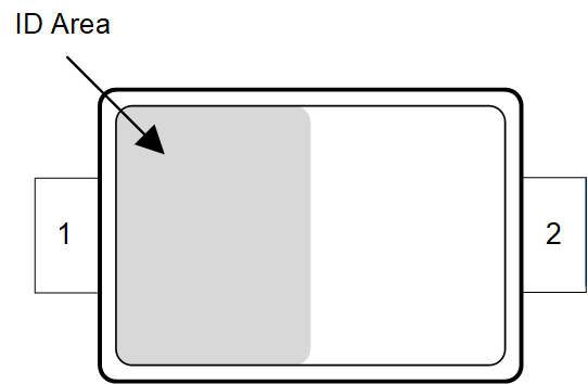
Figure 4-1 DYF Package, 2-Pin SOD-323 (Top View)
Table 4-1 Pin Functions
| PIN | TYPE(1) | DESCRIPTION | |
|---|---|---|---|
| NO. | NAME | ||
| 1 | IO | I/O | Protected Channel. If used as IO, connect pin 2 to ground |
| 2 | IO | I/O | Protected Channel. If used as IO, connect pin 1 to ground |
(1) I = input, O = output