SLOSEC0 December 2023 TX75E16
PRODUCTION DATA
- 1
- 1Features
- 2Applications
- 3Description
- 4Device and Documentation Support
- 5Revision History
- 6Mechanical, Packaging, and Orderable Information
Package Options
Mechanical Data (Package|Pins)
- ALH|144
Thermal pad, mechanical data (Package|Pins)
Orderable Information
3 Description
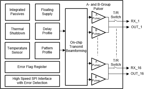
The TX75E16 is a highly integrated, high-performance transmitter for ultrasound imaging system. The device has total 16 pulser circuits, 16 transmit/receive switches (referred as T/R or TR switches), and supports on-chip beamformer (TxBF). The device also integrates on-chip floating power supplies that reduce the number of required high voltage power supplies.
The TX75E16 has a pulser circuit that generates five-level high voltage pulses (up to ±100 V) that is used to excite multiple channels of an ultrasound transducer. The device supports total 16 outputs. The maximum output current is 2 A.
The device can be used as a transmitter for many applications like ultrasound imaging, non-destructive testing, SONAR, LIDAR, marine navigation system, brain imaging systems and so on.
The TX75E16 (referred as device in this data sheet) is highly integrated transmitter targeted for exciting ultrasound transducers. Device integrates 16 pulsers and 16 T/R switches, on-chip beamformer, and pattern generator.
The device integrates all the decoupling capacitors required for the floating supplies and internal bias voltages. This integration significantly reduces the required number of external capacitors. The TX75E16 is available in a 10-mm × 10-mm 144-pin FC-BGA package (ALH package) and is specified for operation from 0°C to 70°C.
Pulser circuit generates five-level high voltage pulses (up to ±100 V) with maximum output current of 2 A. When pulser transmits the high voltage pulses, T/R switch turns OFF and protects the low voltage receiver circuit from damage. When the transducer is receiving echo signals, the T/R switch turns ON and connects the transducer to the receiver. The ON/OFF operation of the T/R switch is controlled by on-chip beamforming engine in the device. The T/R switch offers 8-Ω impedance in the ON state.
Ultrasound transmission relies on excitation of multiple transducer elements, with different delay values defining the direction of the transmission. Such an operation is referred to as transmit beamforming. The TX75E16 supports staggered pulsing of the different channels, allowing for transmit beamforming.
In the on-chip beamformer mode, delay profile for pulsing of different channels is stored within the device. The device supports a transmit beamformer delay resolution of one beamformer clock period and a maximum delay of 214 beamformer clock periods. An internal pattern generator generates the output pulse patterns based on pattern profiles stored in a profile RAM. Each channel has a RAM, which is 960 words long. The patterns have global and local repeats feature. This capability can be used to generate long patterns and can be used in Shear-Wave imaging.
These pattern profiles and delay profiles are written using a high-speed (400 MHz) serial peripheral interface. The high-speed writes can be prone to errors, therefore the device has a checksum feature to detect errors in SPI writes.
To protect the device from getting damaged because of improper configuration, an internal error flag register can detect faulty condition and configure the device in shutdown mode automatically.
 Simplified Block Diagram