SLUS846D September 2008 – August 2024 UCC25600
PRODUCTION DATA
- 1
- 1 Features
- 2 Applications
- 3 Description
- 4 Revision History
- 5 Pin Configuration and Functions
- 6 Specifications
- 7 Detailed Description
- 8 Application and Implementation
- 9 Power Supply Recommendations
- 10Layout
- 11Device and Documentation Support
- 12Glossary
- 13Mechanical, Packaging, and Orderable Information
Package Options
Mechanical Data (Package|Pins)
- D|8
Thermal pad, mechanical data (Package|Pins)
Orderable Information
7.3.1 Soft Start
During start-up and fault recovery conditions, soft start is always implemented to prevent excessive resonant tank current and to ensure zero-voltage switching (ZVS). During soft start, the switching frequency is increased. The soft-start time can be programmed by placing a capacitor from the SS pin to ground.
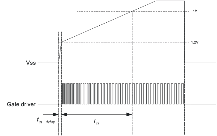
The soft-start pin also serves as an ON/OFF control pin of the device. By actively pulling the SS pin below 1 V, the device is disabled. When the pulldown is removed, SS pin voltage is increased because of internal charging current. Once the SS pin is above 1.2 V, the device starts to generate a gate-driver signal and enters soft-start mode. The time sequence of soft start is shown in Figure 7-1.
 Figure 7-1 Soft-Start Sequence
To prevent a long delay between the ON command and appearance of a gate driver signal, the SS pin current is set as two different levels. When the SS pin voltage is below 1.2 V, its output current is 175 μA. This high current could charge the soft-start pin capacitor to 1.2 V in a short period of time, and reduce the time delay. This time delay can be calculated using following equation:

The switching frequency during soft start is determined by both the current flowing out of the RT pin and the voltage on the SS pin. The switching frequency can be calculated based on the following equation:

After the SS pin voltage reaches 4 V, the soft-start period is finished and switching frequency becomes the same as demanded by the RT pin current. The time used to charge the SS pin from 1.2 V to 4 V is defined as soft-start time and can be calculated as:

To ensure reliable operation, the gate drivers restart with GD2 turning high. This prevents uncertainty during system start up.