SLUSDX3C november 2020 – august 2023 UCC25800-Q1
PRODUCTION DATA
- 1
- 1 Features
- 2 Applications
- 3 Description
- 4 Revision History
- 5 Device Comparison Table
- 6 Pin Configuration and Functions
- 7 Specifications
- 8 Detailed Description
- 9 Application and Implementation
- 10Power Supply Recommendations
- 11Layout
- 12Device and Documentation Support
- 13Mechanical, Packaging, and Orderable Information
Package Options
Mechanical Data (Package|Pins)
- DGN|8
Thermal pad, mechanical data (Package|Pins)
Orderable Information
8.3.6.1 FAULT Codes
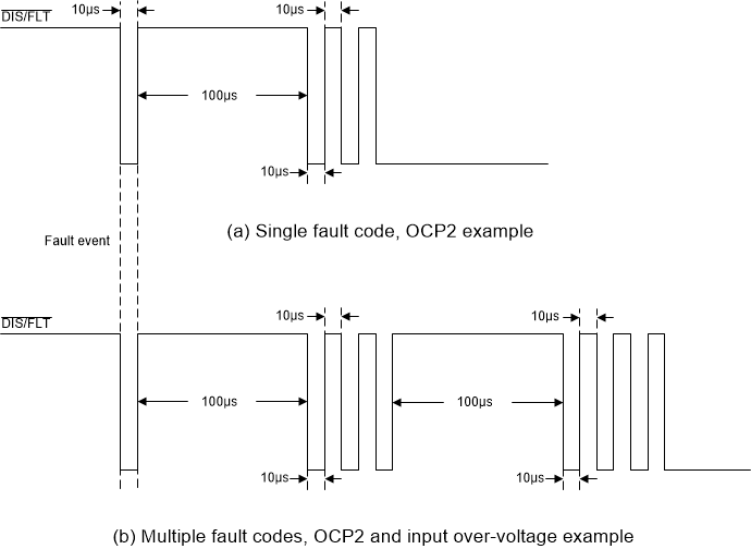
When the UCC25800-Q1 transformer driver enters fault mode, it outputs a train of pulses to indicate which faults have occurred through the DIS/FLT pin. The pulse train consists of a number 50% duty cycle pulses at 50 kHz, (that is, 10-μs wide pulses), where the number of pulses indicates the fault listed in Table 8-4. The pulse train is created through controlling the internal 750-μA pull-down current source, together with the 100-kΩ pull-up resistor.
| NO. OF PULSES | FAULT |
|---|---|
| 1 | OCP1 |
| 2 | OCP2 |
| 3 | Input overvoltage protection |
| 4 | Over temperature protection |
| 5 | DT out of range |
| 6 | OC/DT open |
| 7 | OC/DT short |
| 8 | RT short |
| 9 | OTP (one-time-programmable bit ) error |
The pulse train starts 10 µs after the fault has been asserted. Transmission of the fault code begins with a 100-µs wide high pulse. If more than one fault is detected, the codes are transmitted successively based on the order in Table 8-4, separated by a 100-μs wide high pulse, as shown below in Figure 8-18.
 Figure 8-18 Fault code diagram