SLVSCE4C December 2013 – September 2024 UCC27532-Q1
PRODUCTION DATA
- 1
- 1 Features
- 2 Applications
- 3 Description
- 4 Description (continued)
- 5 Pin Configuration and Functions
- 6 Specifications
- 7 Detailed Description
- 8 Application and Implementation
- 9 Power Supply Recommendations
- 10Layout
- 11Device and Documentation Support
- 12Revision History
- 13Mechanical, Packaging, and Orderable Information
Package Options
Mechanical Data (Package|Pins)
- DBV|6
Thermal pad, mechanical data (Package|Pins)
Orderable Information
8.2.2 Driving IGBT With 13-V Negative Turnoff Bias
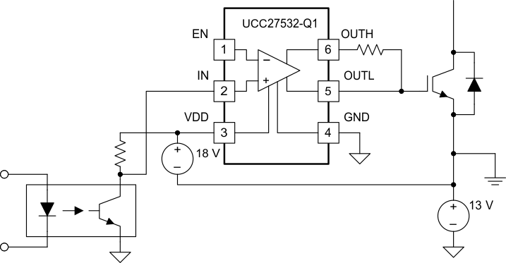
The circuit configuration in Figure 8-5 includes an addition 13-V supply, which is configured to bias the gate of the IGBT at 13-V negative with respect to its emitter. The negative voltage on the gate terminal ensures safe turn off of the IGBT and ensures that the IGBT remains in the blocking state in the presence of high dv/dt voltages on the collector terminal.
 Figure 8-5 Driving IGBT With 13-V Negative Turnoff Bias Schematic