SLUSCK4C September 2016 – October 2024 UCC28950-Q1 , UCC28951-Q1
PRODUCTION DATA
- 1
- 1 Features
- 2 Applications
- 3 Description
- 4 Pin Configuration and Functions
- 5 Specifications
-
6 Detailed Description
- 6.1 Overview
- 6.2 Functional Block Diagram
- 6.3
Feature Description
- 6.3.1 Start-Up Protection Logic
- 6.3.2 Voltage Reference (VREF)
- 6.3.3 Error Amplifier (EA+, EA–, COMP)
- 6.3.4 Soft-Start and Enable (SS/EN)
- 6.3.5 Light-Load Power Saving Features
- 6.3.6 Adaptive Delay, (Delay Between OUTA and OUTB, OUTC and OUTD (DELAB, DELCD, ADEL))
- 6.3.7 Adaptive Delay (Delay Between OUTA and OUTF, OUTB and OUTE (DELEF, ADELEF)
- 6.3.8 Minimum Pulse (TMIN)
- 6.3.9 Burst Mode
- 6.3.10 Switching Frequency Setting
- 6.3.11 Slope Compensation (RSUM)
- 6.3.12 Dynamic SR ON/OFF Control (DCM Mode)
- 6.3.13 Current Sensing (CS)
- 6.3.14 Cycle-by-Cycle Current Limit Current Protection and Hiccup Mode
- 6.3.15 Synchronization (SYNC)
- 6.3.16 Outputs (OUTA, OUTB, OUTC, OUTD, OUTE, OUTF)
- 6.3.17 Supply Voltage (VDD)
- 6.3.18 Ground (GND)
- 6.4 Device Functional Modes
-
7 Application and Implementation
- 7.1 Application Information
- 7.2
Typical Application
- 7.2.1 Design Requirements
- 7.2.2
Detailed Design Procedure
- 7.2.2.1 Power Loss Budget
- 7.2.2.2 Preliminary Transformer Calculations (T1)
- 7.2.2.3 QA, QB, QC, QD FET Selection
- 7.2.2.4 Selecting LS
- 7.2.2.5 Selecting Diodes DB and DC
- 7.2.2.6 Output Inductor Selection (LOUT)
- 7.2.2.7 Output Capacitance (COUT)
- 7.2.2.8 Select FETs QE and QF
- 7.2.2.9 Input Capacitance (CIN)
- 7.2.2.10 Current Sense Network (CT, RCS, R7, DA)
- 7.2.3 Application Curves
- 7.3 Power Supply Recommendations
- 7.4 Layout
- 8 Device and Documentation Support
- 9 Revision History
- 10Mechanical, Packaging, and Orderable Information
Package Options
Mechanical Data (Package|Pins)
- PW|24
Thermal pad, mechanical data (Package|Pins)
Orderable Information
6.3.14 Cycle-by-Cycle Current Limit Current Protection and Hiccup Mode
The cycle-by-cycle current limit provides peak current limiting on the primary side of the converter when the load current exceeds its predetermined threshold. For peak current mode control, a certain leading edge blanking time is needed to prevent the controller from false tripping due to switching noise. An internal 30ns filter at the CS input is provided. The total propagation delay TCS from CS pin to outputs is 100ns. An external RC filter is still needed if the power stage requires more blanking time. The 2.0V ±3% cycle-by-cycle current limit threshold is optimized for efficient current transformer based sensing. The duration when a converter operates at cycle-by-cycle current limit depends on the value of soft-start capacitor and how severe the overcurrent condition is. This is achieved by the internal discharge current IDS Equation 16 and Equation 17 at SS pin.
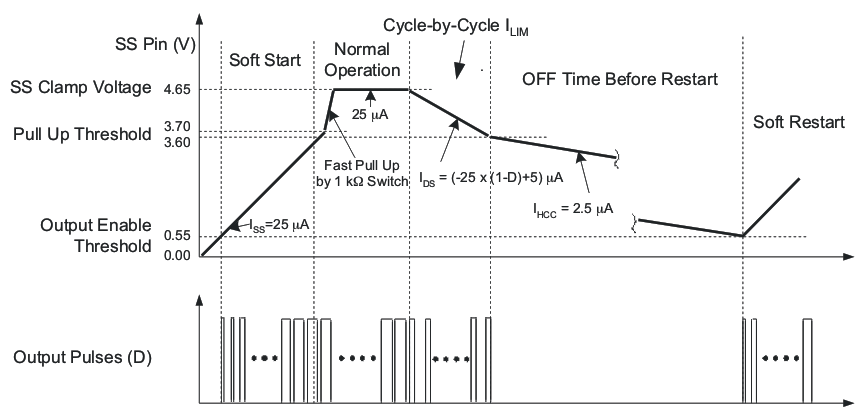
The soft-start capacitor value also determines the so-called hiccup mode off-time duration. The behavior of the converter during different modes of operation, along with related soft-start capacitor charge and discharge currents are shown in Figure 6-15.
 Figure 6-15 Timing
Diagram of Soft-Start Voltage VSS
Figure 6-15 Timing
Diagram of Soft-Start Voltage VSSThe largest discharge current of 20µA is when the duty cycle is close to zero. This current sets the shortest operation time during the cycle-by-cycle current limit and is defined in Equation 18 and Equation 19
Thus, if the soft-start capacitor CSS = 100nF is selected, then the TCL(on) time is 5ms.
To calculate the hiccup off time TCL(off) before the restart, use Equation 20 or Equation 21.
With the same soft-start capacitor value at 100nF, the off-time before the restart is 122ms. If the overcurrent condition occurs before the soft-start capacitor voltage reaches the 3.7V threshold during start-up, the controller limits the current but the soft-start capacitor continues to be charged. As soon as the 3.7V threshold is reached, the soft-start voltage is quickly pulled up to the 4.65V threshold by an internal 1kΩ RDS(on) switch and the cycle-by-cycle current limit duration timing starts by discharging the soft-start capacitor. Depending on specific design requirements, the user can override this default behavior by applying external charge or discharge currents to the soft-start capacitor. The whole cycle-by-cycle current limit and hiccup operation is shown in Figure 6-15. In this example, the cycle-by-cycle current limit lasts about 5ms followed by 122ms of off-time.
Similarly to the overcurrent condition, the hiccup mode with the restart can be disabled by the user if a pullup resistor of 261kΩ is connected between the SS and VREF pins. The controller remains in the latch-off mode if an overcurrent condition occurs. In this case, calculate an external soft-start capacitor value with the additional pullup current taken into account. The latch-off mode can be reset externally if the soft-start capacitor is forcibly discharged below 0.55V or the VDD voltage is lowered below the UVLO threshold.