-
ULN2003LV 7-Channel Relay and Inductive Load Sink Driver
- 1 Features
- 2 Applications
- 3 Description
- 4 Revision History
- 5 Pin Configuration and Functions
- 6 Specifications
- 7 Detailed Description
- 8 Application and Implementation
- 9 Power Supply Recommendations
- 10Layout
- 11Device and Documentation Support
- 12Mechanical, Packaging, and Orderable Information
- IMPORTANT NOTICE
Package Options
Mechanical Data (Package|Pins)
Thermal pad, mechanical data (Package|Pins)
Orderable Information
ULN2003LV 7-Channel Relay and Inductive Load Sink Driver
1 Features
- 7-Channel High Current Sink Drivers
- Supports up to 8V Ouput Pullup Voltage
- Supports a Wide Range of 3V-to-5V Relay and Inductive Coils
- Low Output VOL of 0.4V (Typical) With
- 100mA (Typical) Current Sink per Channel at 3.3V Logic Input(1)
- 140mA (Typical) Current Sink per Channel at 5.0V Logic Input(1)
- Compatible to 3.3V and 5.0V Microcontrollers and Logic Interface
- Internal Free-Wheeling Diodes for Inductive Kick-back Protection
- Input Pulldown Resistors Allows3-stating the Input Driver
- Input RC-Snubber to Eliminate Spurious Operation in Noisy Environment
- Low Input and Output Leakage Currents
- Easy to use Parallel Interface
- ESD Protection Exceeds JESD 22
- 2kV HBM, 500V CDM
- Available in 16-Pin SOIC and TSSOP Packages (1)
2 Applications
- Relay and Inductive Load Driver in Various Telecom, Consumer, and Industrial Applications
- Lamp and LED Displays
- Logic Level Shifter
3 Description
The ULN2003LV is a low-voltage and low power upgrade of TI’s popular ULN2003 family of 7-channel Darlington transistor array. The ULN2003LV sink driver features 7 low output impedance drivers to support low voltage relay and inductive coil applications. The low impedance drivers minimize on-chip power dissipation; up to 5 times lower for typical 3V relays. The ULN2003LV driver is pin-to-pin compatible with ULN2003 family of devices in similar packages.
The ULN2003LV supports 3.3V to 5V CMOS logic input interface thus making it compatible to a wide range of micro-controllers and other logic interfaces. The ULN2003LV features an improved input interface that minimizes the input DC current drawn from the external drivers. The ULN2003LV features an input RC snubber that greatly improves its performance in noisy operating conditions. The ULN2003LV channel inputs feature an internal input pull-down resistor thus allowing input logic to be tri-stated. The ULN2003LV may also support other logic input levels, for example, TTL and 1.8V, refer to the Application Information section for details.
The ULN2003LV provides flexibility of increasing current sink capability through combining several adjacent channels in parallel. Under typical conditions the ULN2003LV can support up to 1.0A of load current when all 7-channels are connected in parallel. The ULN2003LV can also be used in a variety of applications requiring a sink drivers like driving LEDs and Logic Level Shifting.
Device Information(1)
| PART NUMBER | PACKAGE | BODY SIZE (NOM) |
|---|---|---|
| ULN2003LVDR | SOIC (16) | 3.90 mm x 9.90 mm |
| ULN2003LVPWR | TSSOP (16) | 4.40 mm x 5.00 mm |
- For all available packages, see the orderable addendum at the end of the data sheet.
Simplified Function Diagram

4 Revision History
Changes from A Revision (April 2012) to B Revision
- Added Pin Configuration and Functions section, ESD Ratings table, Feature Description section, Device Functional Modes, Application and Implementation section, Power Supply Recommendations section, Layout section, Device and Documentation Support section, and Mechanical, Packaging, and Orderable Information section Go
5 Pin Configuration and Functions
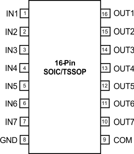
Pin Functions
| PIN | TYPE | DESCRIPTION | |
|---|---|---|---|
| NAME | NO. | ||
| IN1 | 1 | Input | Logic Input Pins IN1 through IN7 |
| IN2 | 2 | Input | |
| IN3 | 3 | Input | |
| IN4 | 4 | Input | |
| IN5 | 5 | Input | |
| IN6 | 6 | Input | |
| IN7 | 7 | Input | |
| GND | 8 | Ground | Ground Reference Pin |
| COM | 9 | Output | Internal Free-Wheeling Diode Common Cathode Pin |
| OUT7 | 10 | Output | Channel Output Pins OUT7 through OUT1 |
| OUT6 | 11 | Output | |
| OUT5 | 12 | Output | |
| OUT4 | 13 | Output | |
| OUT3 | 14 | Output | |
| OUT2 | 15 | Output | |
| OUT1 | 16 | Output | |
6 Specifications
6.1 Absolute Maximum Ratings
Specified at TJ = –40°C to 125°C unless otherwise noted.(1)| MIN | MAX | UNIT | |||
|---|---|---|---|---|---|
| VIN | Pins IN1- IN7 to GND voltage | –0.3 | 5.5 | V | |
| VOUT | Pins OUT1 – OUT7 to GND voltage | 8 | V | ||
| VCOM | Pin COM to GND voltage | 8 | V | ||
| IGND | Maximum GND-pin continuous current (TJ > +125°C) | 700 | mA | ||
| Maximum GND-pin continuous current (TJ < +100°C) | 1.0 | A | |||
| PD | Total device power dissipation at TA = 85°C | 16 Pin - SOIC | 0.58 | W | |
| 16 Pin -TSSOP | 0.45 | W | |||
| TA | Operating free-air ambient temperature | –40 | 85 | °C | |
| TJ | Operating virtual junction temperature | –55 | 150 | °C | |
| Tstg | Storage temperature | –55 | 150 | °C | |
6.2 ESD Ratings
| VALUE | UNIT | |||
|---|---|---|---|---|
| V(ESD) | Electrostatic discharge | Human body model (HBM), per ANSI/ESDA/JEDEC JS-001(1) | ±2000 | V |
| Charged-device model (CDM), per JEDEC specification JESD22-C101(2) | ±500 | |||
6.3 Recommended Operating Conditions
over operating free-air temperature range (unless otherwise noted)| MIN | MAX | UNIT | |||
|---|---|---|---|---|---|
| VOUT | Channel off-state output pullup voltage | 8 | V | ||
| VCOM | COM pin voltage | 8 | V | ||
| IOUT(ON) | Per channel continuous sink current | VINx = 3.3 V | 100(1) | mA | |
| VINx = 5.0 V | 140(1) | ||||
| TJ | Operating junction temperature | –40 | 125 | ºC | |
6.4 Thermal Information
| THERMAL METRIC(1) | ULN2003LV | UNIT | ||
|---|---|---|---|---|
| D (SOIC) | PW (TSSOP) | |||
| 16 PINS | 16 PINS | |||
| RθJA | Junction-to-ambient thermal resistance | 112 | 142 | °C/W |
| RθJC(top) | Junction-to-case (top) thermal resistance | 69 | 74 | °C/W |
| RθJB | Junction-to-board thermal resistance | 69 | 87 | °C/W |
| ψJT | Junction-to-top characterization parameter | 33 | 22 | °C/W |
| ψJB | Junction-to-board characterization parameter | 69 | 87 | °C/W |
6.5 Electrical Characteristics
Specified over the recommended junction temperature range TJ = –40°C to 125°C unless otherwise noted. Typical values are at TJ = 25°C.| PARAMETER | TEST CONDITIONS | MIN | TYP | MAX | UNIT | |
|---|---|---|---|---|---|---|
| INPUTS IN1 THROUGH IN7 PARAMETERS | ||||||
| VI(ON) | IN1–IN7 logic high input voltage | Vpull-up = 3.3 V, Rpullup = 1 kΩ, IOUTX = 3.2 mA | 1.65 | V | ||
| VI(OFF) | IN1–IN7 logic low input voltage | Vpullup = 3.3 V, Rpullup = 1 kΩ, (IOUTX = <5 µA) |
0.4 | 0.6 | V | |
| II(ON) | IN1–IN7 ON state input current | Vpullup = 3.3 V, VINx = 3.3 V | 12 | 25 | µA | |
| II(OFF) | IN1–IN7 OFF state input leakage | Vpullup = 3.3 V, VINx = 0 V | 250 | nA | ||
| OUTPUTS OUT1 THROUGH OUT7 PARAMETERS | ||||||
| VOL(VCE-SAT) | OUT1–OUT7 low-level output voltage | VINX = 3.3 V, IOUTX = 50 mA | 0.17 | 0.24 | V | |
| VINX = 3.3 V, IOUTX = 100 mA | 0.36 | 0.49 | ||||
| VINX = 5.0 V, IOUTX = 100 mA | 0.26 | 0.42 | ||||
| VINX = 5.0 V, IOUTX = 140 mA | 0.40 | |||||
| IOUT(ON) | OUT1–OUT7 ON-state continuous current(1)(2) at VOUTX = 0.4V | VINX = 3.3 V, VOUTX = 0.4 V | 80 | 100 | mA | |
| VINX = 5.0 V, VOUTX = 0.4 V | 95 | 140 | ||||
| IOUT(OFF)(ICEX) | OUT1–OUT7 OFF-state leakage current | VINX = 0 V, VOUTX = VCOM = 8 V | 0.17 | µA | ||
| FREE-WHEELING DIODE PARAMETERS(3)(4) | ||||||
| VF | Forward voltage drop | IF-peak = 140 mA, VF = VOUTx – VCOM, | 1.2 | V | ||
| IF-peak | Diode peak forward current | 140 | mA | |||
6.6 Switching Characteristics
over operating free-air temperature range (unless otherwise noted)(1)(2)| PARAMETER | TEST CONDITIONS | MIN | TYP | MAX | UNIT | |
|---|---|---|---|---|---|---|
| tPHL | OUT1–OUT7 logic high propagation delay | VINX = 3.3V, Vpull-up = 3.3 V, Rpull-up = 50 Ω | 25 | ns | ||
| VINX = 5.0V, Vpull-up = 5 V, Rpull-up = 1 kΩ | 15 | |||||
| tPLH | OUT1–OUT7 logic low propagation delay | VINX = 3.3V, Vpull-up = 3.3 V, Rpull-up = 50 Ω | 45 | ns | ||
| VINX = 5.0V, Vpull-up = 5 V, Rpull-up = 1kΩ | 80 | |||||
| RPD | IN1–IN7 input pull-down Resistance | 210 | 300 | 390 | kΩ | |
| ζ | IN1–IN7 Input filter time constant | 9 | ns | |||
| COUT | OUT1–OUT7 output capacitance | VINX = 3.3 V, VOUTX = 0.4 V | 15 | pF | ||
6.7 Dissipation Ratings
See (1)(3)| BOARD | PACKAGE | RθJC | RθJA(2) | DERATING FACTOR ABOVE TA = 25ºC | TA < 25°C | TA = 70°C | TA = 85°C |
|---|---|---|---|---|---|---|---|
| High-K | 16-Pin SOIC | 69°C/W | 112°C/W | 8.88 mW/ºC | 1.11 W | 0.71 W | 0.58 W |
| High-K | 16-Pin TSSOP | 74°C/W | 142°C/W | 7.11 mW/ºC | 0.88 W | 0.56 W | 0.45 W |
6.8 Typical Characteristics
TA = +25ºC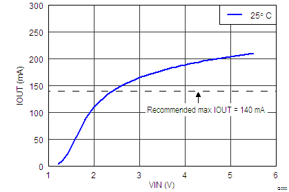 Figure 1. Load Current 1-Channel; VOL=0.4V
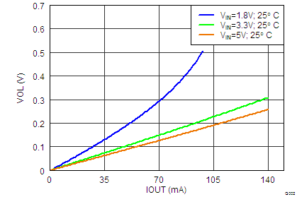 Figure 3. VOL versus IOUT VIN = 1.8V, 3.3V, 5.0V
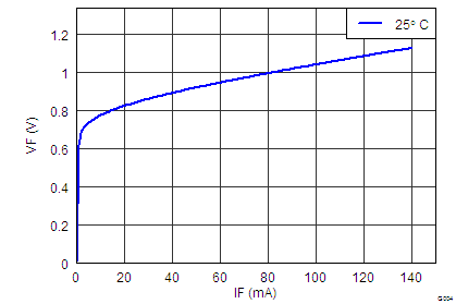 Figure 5. Freewheeling Diode VF vs IF
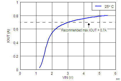 Figure 2. Load Current 7-Channels in Parallel; VOL=0.4V
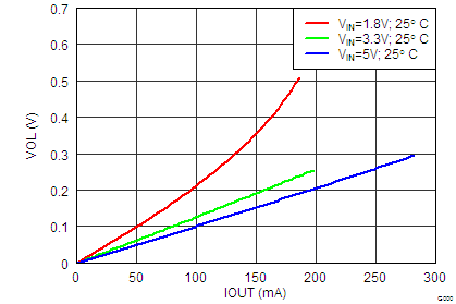 Figure 4. VOL versus IOUT 2-Channels in Parallel; VOL=0.4V