SLRS060C May 2012 – November 2016 ULN2003V12
PRODUCTION DATA.
- 1 Features
- 2 Applications
- 3 Description
- 4 Revision History
- 5 Pin Configuration and Functions
- 6 Specifications
- 7 Detailed Description
- 8 Applications and Implementation
- 9 Power Supply Recommendations
- 10Layout
- 11Device and Documentation Support
- 12Mechanical, Packaging, and Orderable Information
Package Options
Mechanical Data (Package|Pins)
Thermal pad, mechanical data (Package|Pins)
Orderable Information
7 Detailed Description
7.1 Overview
The ULN2003V12 device is a seven channel low-side NMOS driver capable of driving 100-mA Load with 3-V input drive voltage through each channel. This device can drive relays, LEDs, or resistive loads up to 16 V. The ULN2003V12 supports 3.3-V to 5-V CMOS logic input interface, thus making it compatible to a wide range of microcontrollers and other logic interfaces. The ULN2003V12 features an improved input interface that minimizes the input DC current drawn from the external drivers. The ULN2003V12 features an input RC snubber that greatly improves its performance in noisy operating conditions. The ULN2003V12 channel inputs feature an internal input pulldown resistor, thus allowing input logic to be tri-stated. The ULN2003V12 may also support other logic input levels (for example, TTL and 1.8 V).
7.2 Functional Diagram

7.3 Feature Description
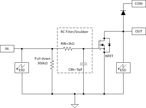
As shown in Figure 3, each output of the ULN2003V12 features an internal free-wheeling diode connected in a common-cathode configuration at the COM pin. The ULN2003V12 provides flexibility of increasing current sink capability through combining several adjacent channels in parallel. Under typical conditions, the ULN2003V12 can support up to 1 A of load current when all 7-channels are connected in parallel. The ULN2003V12 can also be used in a variety of other applications requiring a sink driver.
 Figure 3. Channel Block Diagram
7.3.1 TTL and Other Logic Inputs
ULN2003V12 input interface is specified for standard 3-V and 5-V CMOS logic interface. However, ULN2003V12 input interface may support other logic input levels as well. See Figure 1 and Figure 2 to establish VOL and the corresponding typical load current levels for various input voltage ranges. See Applications and Implementation for an implementation to drive 1.8-V relays using ULN2003V12.
7.3.2 Input RC Snubber
ULN2003V12 features an input RC snubber that helps prevent spurious switching in noisy environment. Connect an external 1-kΩ to 5-kΩ resistor in series with the input to further enhance ULN2003V12’s noise tolerance.
7.3.3 High-impedance Input Drivers
ULN2003V12 features a 300-kΩ input pulldown resistor. The presence of this resistor allows the input drivers to be tri-stated. When a high-impedance driver is connected to a channel input the ULN2003V12 detects the channel input as a low level input and remains in the OFF position. The input RC snubber helps improve noise tolerance when input drivers are in the high-impedance state.