SBOS061C February   1997  – October 2024 XTR105

PRODUCTION DATA  

  1.   1
  2. Features
  3. Applications
  4. Description
  5. Pin Configuration and Functions
  6. Specifications
    1. 5.1 Absolute Maximum Ratings #GUID-80F0CD5F-C345-42B2-B6A9-580512790460/R_DESCRIPTION_LI1
    2. 5.2 Recommended Operating Conditions
    3. 5.3 Thermal Information
    4. 5.4 Electrical Characteristics
    5. 5.5 Typical Characteristics
  7. Detailed Description
    1. 6.1 Overview
    2. 6.2 Functional Block Diagram
    3. 6.3 Feature Description
      1. 6.3.1 Linearization
        1. 6.3.1.1 High-Resistance RTDs
      2. 6.3.2 Voltage Regulator
      3. 6.3.3 Open-Circuit Protection
      4. 6.3.4 Reverse-Voltage Protection
      5. 6.3.5 Surge Protection
    4. 6.4 Device Functional Modes
  8. Application and Implementation
    1. 7.1 Application Information
      1. 7.1.1 External Transistor
      2. 7.1.2 Loop Power Supply
      3. 7.1.3 2-Wire and 3-Wire RTD Connections
      4. 7.1.4 Radio Frequency Interference
      5. 7.1.5 Error Analysis
    2. 7.2 Typical Applications
    3. 7.3 Layout
      1. 7.3.1 Layout Guidelines
  9. Device and Documentation Support
    1. 8.1 Documentation Support
      1. 8.1.1 Related Documentation
    2. 8.2 Receiving Notification of Documentation Updates
    3. 8.3 Support Resources
    4. 8.4 Trademarks
    5. 8.5 Electrostatic Discharge Caution
    6. 8.6 Glossary
  10. Revision History
  11. 10Mechanical, Packaging, and Orderable Information

Package Options

Refer to the PDF data sheet for device specific package drawings

Mechanical Data (Package|Pins)
  • D|14
  • N|14
Thermal pad, mechanical data (Package|Pins)
Orderable Information

Open-Circuit Protection

Optional transistor Q2 in Figure 6-3 provides predictable behavior with open-circuit RTD connections. If any one of the three RTD connections is broken, the XTR105 output current goes to either the high current limit (≅ 27mA) or low current limit (≅ 2.2mA). This state is easily detected as an out-of-range condition.
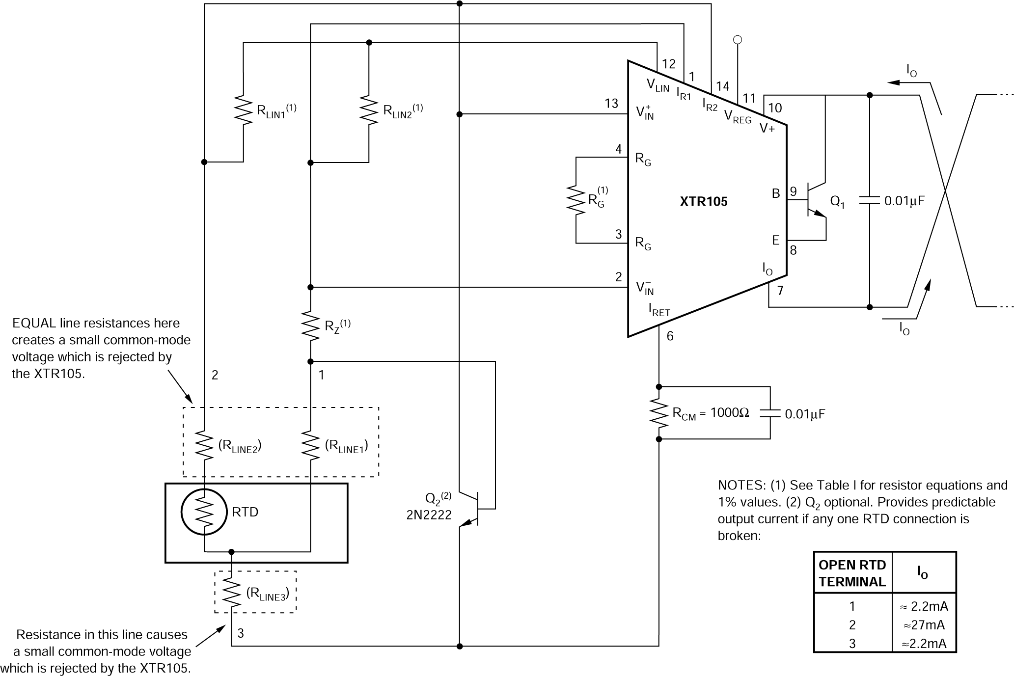
XTR105 Remotely Located RTDs With a 3-Wire
                                                  Connection Figure 6-3 Remotely Located RTDs With a 3-Wire Connection