SBOS375D October 2006 – October 2024 XTR111
PRODUCTION DATA
- 1
- 1 Features
- 2 Applications
- 3 Description
- 4 Pin Configurations and Functions
- 5 Specifications
- 6 Detailed Description
- 7 Application and Implementation
- 8 Device and Documentation Support
- 9 Revision History
- 10Mechanical, Packaging, and Orderable Information
Package Options
Refer to the PDF data sheet for device specific package drawings
Mechanical Data (Package|Pins)
- DRC|10
- DGQ|10
Thermal pad, mechanical data (Package|Pins)
Orderable Information
7.1.4 4mA-to-20mA Output
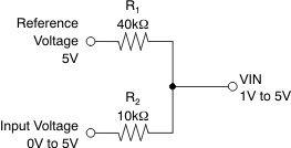
The XTR111 does not provide internal circuits to generate 4mA with 0V input signal. Figure 7-3 shows that the most common way to shift the input signal is a two-resistor network connected to a voltage reference and the signal source. This arrangement allows easy adjustment for overrange and underrange conditions. The example assumes a 5V reference (VREF) that equals the full-scale signal voltage and a signal span of 0V to 5V for 4mA-to-20mA (IMIN to IMAX) output.
The voltage regulator output or a more precise reference can be used as VREF. Observe the potential drift added by the drift of the resistors and the voltage reference.
 Figure 7-3 Resistive
Divider for IMIN-to-IMAX Output (4mA to 20mA) With 0V to
VFS Signal Source