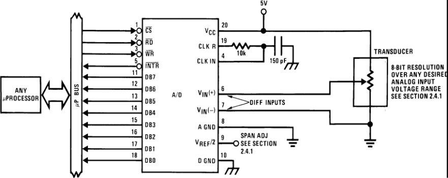
The ADC0801, ADC0802, ADC0803, ADC0804, and ADC0805 devices are CMOS 8-bit successive approximation converters (ADC) that use a differential potentiometric ladder — similar to the 256R products. These converters are designed to allow operation with the NSC800 and INS8080A derivative control bus with Tri-state output latches directly driving the data bus. These ADCs appear like memory locations or I/O ports to the microprocessor and no interfacing logic is needed.
Differential analog voltage inputs allow increasing the common-mode rejection and offsetting the analog zero input voltage value. In addition, the voltage reference input can be adjusted to allow encoding any smaller analog voltage span to the full 8 bits of resolution.
PART NUMBER | PACKAGE | BODY SIZE (NOM) |
---|---|---|
ADC0801, ADC0803 | PDIP (20) | 26.073 mm × 6.604 mm |
ADC0802, ADC0804 | PDIP (20) | 26.073 mm × 6.604 mm |
SOIC (20) | 12.80 mm × 7.50 mm |
Changes from B Revision (Feburary 2013) to C Revision
PIN | I/O | DESCRIPTION | |
---|---|---|---|
NO. | NAME | ||
1 | CS | I | Chip Select |
2 | RD | I | Read |
3 | WR | I | Write |
4 | CLK IN | I | External Clock input or use internal clock gen with external RC elements |
5 | INTR | O | Interrupt request |
6 | VIN(+) | I | Differential analog input+ |
7 | VIN(–) | I | Differential analog input– |
8 | A GND | I | Analog ground pin |
9 | VREF/2 | I | Reference voltage input for adjustment to correct full scale reading |
10 | D GND | I | Digital ground pin |
11 | DB7 | O | Data bit 7 |
12 | DB6 | O | Data bit 6 |
13 | DB5 | O | Data bit 5 |
14 | DB4 | O | Data bit 4 |
15 | DB3 | O | Data bit 3 |
16 | DB2 | O | Data bit 2 |
17 | DB1 | O | Data bit 1 |
18 | DB0 (LSB) | O | Data bit 0 |
19 | CLK R | I | RC timing resistor input pin for internal clock gen |
20 | VCC (or VREF) | I | +5V supply voltage, also upper reference input to the ladder |
MIN | MAX | UNIT | ||
---|---|---|---|---|
Supply voltage (VCC)(2) | 6.5 | V | ||
Voltage | Logic control inputs | –0.3 | 18 | V |
At other input and outputs | –0.3 | (VCC +0.3) | ||
Lead Temperature (Soldering, 10 seconds) | Dual-In-Line Package (plastic | 260 | °C | |
Dual-In-Line Package (ceramic) | 300 | |||
Surface Mount Package Vapor Phase (60 seconds) | 215 | |||
Infrared (15 seconds) | 220 | |||
Storage Temperature | –65 | 150 | ||
Package Dissipation at TA = 25°C | 875 | mW |
VALUE | UNIT | |||
---|---|---|---|---|
V(ESD) | Electrostatic discharge | Human body model (HBM), per ANSI/ESDA/JEDEC JS-001(1) | ±800 | V |
MIN | NOM | MAX | UNIT | ||
---|---|---|---|---|---|
VCC | 4.5 | 5 | 5.5 | V | |
Analog Input Voltage | GND – 0.05 | VCC + 0.05 | VDC |
THERMAL METRIC(1) | ADC080x | ADC0802, ADC0804 | UNIT | |
---|---|---|---|---|
NFH (PDIP) | DW (SOIC) | |||
20 PINS | 20 PINS | |||
RθJA | Junction-to-ambient thermal resistance | 38.5 | 63.8 | °C/W |
RθJC(top) | Junction-to-case (top) thermal resistance | 23.4 | 27.2 | °C/W |
RθJB | Junction-to-board thermal resistance | 19.5 | 31.8 | °C/W |
ψJT | Junction-to-top characterization parameter | 8.7 | 5.7 | °C/W |
ψJB | Junction-to-board characterization parameter | 19.4 | 31.3 | °C/W |
RθJC(bot) | Junction-to-case (bottom) thermal resistance | — | — | °C/W |
MIN | MAX | UNIT | ||
---|---|---|---|---|
Temperature | ADC0804LCJ | –40 | 85 | °C |
ADC0801/02/03/05LCN | –40 | 85 | ||
ADC0804LCN | 0 | 70 | ||
ADC0802/04LCWM | 0 | 70 | ||
Range of VCC | 4.5 | 6.3 | VDC |
PARAMETER | TEST CONDITIONS | MIN | TYP | MAX | UNIT |
---|---|---|---|---|---|
ADC0801: Total Adjusted Error(1) | With Full-Scale Adj. (See Full-Scale) | ±1/4 | LSB | ||
ADC0802: Total Unadjusted Error(1) | VREF/2=2.500 VDC | ±1/2 | |||
ADC0803: Total Adjusted Error(1) | With Full-Scale Adj. (See Full-Scale) | ±1/2 | |||
ADC0804: Total Unadjusted Error (1) | VREF/2=2.500 VDC | ±1 | |||
ADC0805: Total Unadjusted Error (1) | VREF/2-No Connection | ±1 | |||
VREF/2 Input Resistance (Pin 9) | ADC0801/02/03/05 | 2.5 | 8 | kΩ | |
ADC0804 (2) | 0.75 | 1.1 | |||
Analog Input Voltage Range | V(+) or V(–)(3) | GND–0.05 | VCC+0.05 | VDC | |
DC Common-Mode Error | Over Analog Input Voltage Range | ±1/16 | ±1/8 | LSB | |
Power Supply Sensitivity | VCC=5 VDC ±10% Over Allowed VIN(+) and VIN(–) Voltage Range(3) | ±1/16 | ±1/8 | LSB |
PARAMETER | TEST CONDITIONS | MIN | TYP | MAX | UNIT | ||
---|---|---|---|---|---|---|---|
TC | Conversion Time | fCLK = 640 kHz(1) | 103 | 114 | µs | ||
See (2)(1) | 66 | 73 | 1/fCLK | ||||
fCLK | Clock Frequency | VCC = 5V(2) | 100 | 640 | 1460 | kHz | |
Clock Duty Cycle | 40% | 60% | |||||
CR | Conversion Rate in Free-Running Mode | INTR tied to WR with CS = 0 VDC, fCLK = 640 kHz |
8770 | 9708 | conv/s | ||
tW(WR)L | Width of WR Input (Start Pulse Width) | CS = 0 VDC (3) | 100 | ns | |||
tACC | Access Time (Delay from Falling Edge of RD to Output Data Valid) | CL = 100 pF | 135 | 200 | |||
t1H, t0H | Tri-State Control (Delay from Rising Edge of RD to Hi-Z State) | CL = 10 pF, RL = 10k (See Tri-State Test Circuits and Waveforms) | 125 | 200 | |||
tWI, tRI | Delay from Falling Edge of WR or RD to Reset of INTR | 300 | 450 | ||||
CIN | Input Capacitance of Logic Control Inputs | 5 | 7.5 | pF | |||
COUT | Tri-State Output Capacitance (Data Buffers) | 5 | 7.5 | ||||
CONTROL INPUTS [Note: CLK IN (Pin 4) is the input of a Schmitt trigger circuit and is therefore specified separately] | |||||||
VIN (1) | Logical “1” Input Voltage (Except Pin 4 CLK IN) | VCC = 5.25 VDC | 2 | 15 | VDC | ||
VIN (0) | Logical “0” Input Voltage (Except Pin 4 CLK IN) | VCC = 4.75 VDC | 0.8 | ||||
IIN (1) | Logical “1” Input Current (All Inputs) | VIN = 5 VDC | 0.005 | 1 | µADC | ||
IIN (0) | Logical “0” Input Current (All Inputs) | VIN = 0 VDC | –1 | –0.005 | |||
CLOCK IN AND CLOCK R | |||||||
VT+ | CLK IN (Pin 4) Positive Going Threshold Voltage | 2.7 | 3.1 | 3.5 | VDC | ||
VT− | CLK IN (Pin 4) Negative Going Threshold Voltage | 1.5 | 1.8 | 2.1 | |||
VH | CLK IN (Pin 4) Hysteresis (VT+)–(VT−) | 0.6 | 1.3 | 2 | |||
VOUT (0) | Logical “0” CLK R Output Voltage | IO = 360 µA, VCC = 4.75 VDC | 0.4 | ||||
VOUT (1) | Logical “1” CLK R Output Voltage | IO = −360 µA, VCC = 4.75 VDC | 2.4 | ||||
DATA OUTPUTS AND INTR | |||||||
VOUT (0) | Logical “0” Output Voltage | Data Outputs | IOUT = 1.6 mA, VCC = 4.75 VDC | 0.4 | VDC | ||
INTR Output | IOUT = 1.0 mA, VCC = 4.75 VDC | 0.4 | |||||
VOUT (1) | Logical “1” Output Voltage | IO = −360 µA, VCC = 4.75 VDC | 2.4 | ||||
IO = −10 µA, VCC = 4.75 VDC | 4.5 | ||||||
IOUT | Tri-State Disabled Output Leakage (All Data Buffers) | VOUT = 0 VDC | –3 | µADC | |||
VOUT = 5 VDC | 3 | ||||||
ISOURCE | VOUT Short to GND, TA = 2 5°C | 4.5 | 6 | mADC | |||
ISINK | VOUT Short to VCC, TA = 25°C | 9 | 16 | ||||
POWER SUPPLY | |||||||
ICC | Supply Current (Includes Ladder Current) | ADC0801/02/03/04LCJ/05 | fCLK = 640 kHz, VREF/2 = NC, TA = 25°C and CS = 5 V |
1.1 | 1.8 | mA | |
ADC0804LCN/LCWM | 1.9 | 2.5 |
NOTE:
Read strobe must occur 8 clock periods (8/fCLK) after assertion of interrupt to specify reset of INTR.CL = 10 pF |
CL = 10 pF |