-
ADS7044 Ultra-Low Power, Ultra-Small Size, 12-Bit, 1-MSPS, SAR ADC
- 1 Features
- 2 Applications
- 3 Description
- 4 Revision History
- 5 Pin Configuration and Functions
- 6 Specifications
- 7 Parameter Measurement Information
- 8 Detailed Description
- 9 Application and Implementation
- 10Power-Supply Recommendations
- 11Layout
- 12Device and Documentation Support
- 13Mechanical, Packaging, and Orderable Information
- IMPORTANT NOTICE
Package Options
Refer to the PDF data sheet for device specific package drawings
Mechanical Data (Package|Pins)
- DCU|8
- RUG|8
Thermal pad, mechanical data (Package|Pins)
Orderable Information
ADS7044 Ultra-Low Power, Ultra-Small Size, 12-Bit, 1-MSPS, SAR ADC
1 Features
- Industry's First SAR ADC with Nanowatt Power Consumption:
- 261 µW at 1 MSPS with 1.8-V AVDD
- 900 µW at 1 MSPS with 3-V AVDD
- 90 µW at 100 kSPS with 3-V AVDD
- Less than 1 µW at 1 kSPS with 3-V AVDD
- Industry's Smallest SAR ADC:
- X2QFN-8 Package with 2.25-mm2 Footprint
- 1-MSPS Throughput with Zero Data Latency
- Wide Operating Range:
- Excellent Performance:
- 12-Bit Resolution with NMC
- ±1-LSB (Max) DNL and INL
- 71-dB SNR with 3-V AVDD
- –85-dB THD with 3-V AVDD
-
Unipolar, Differential Input Range:
–AVDD to AVDD - Integrated Offset Calibration
- SPI™-Compatible Serial Interface: 16 MHz
- JESD8-7A Compliant Digital I/O
2 Applications
- Low-Power Data Acquisition
- Battery-Powered Handheld Equipment
- Level Sensors
- Ultrasonic Flow Meters
- Motor Controls
- Wearable Fitness
- Portable Medical Equipment
- Hard Drives
- Glucose Meters
3 Description
The ADS7044 is a 1-MSPS, analog-to-digital converter (ADC). The device supports a wide analog input voltage range (±1.65 V to ±3.6 V) and includes a capacitor-based, successive-approximation register (SAR) ADC with an inherent sample-and-hold circuit. The SPI-compatible serial interface is controlled by the CS and SCLK signals. The input signal is sampled with the CS falling edge and SCLK is used for conversion and serial data output. The device supports a wide digital supply range (1.65 V to 3.6 V), enabling direct interface to a variety of host controllers. The device complies with the JESD8-7A standard for normal DVDD range (1.65 V to 1.95 V).
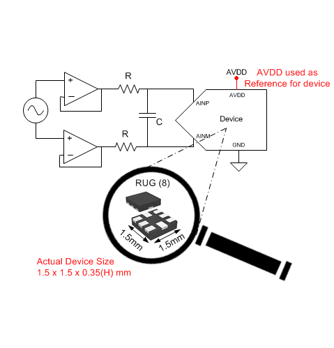
The device is available in 8-pin, miniature, leaded, and X2QFN packages and is specified for operation from –40°C to 125°C. Miniature form-factor and extremely low-power consumption make this device suitable for space-constrained, battery-powered applications.
Device Information(1)
| PART NAME | PACKAGE | BODY SIZE (NOM) |
|---|---|---|
| ADS7044 | X2QFN (8) | 1.50 mm × 1.50 mm |
| VSSOP (8) | 2.30 mm × 2.00 mm |
- For all available packages, see the orderable addendum at the end of the datasheet.
space
space
space
Typical Application

4 Revision History
Changes from C Revision (February 2015) to D Revision
- Changed Figure 1Go
- Changed Serial Interface section: changed last half of first paragraph, changed Figure 35Go
- Changed Figure 38Go
- Added Community Resources section Go
Changes from B Revision (December 2014) to C Revision
- Changed Wide Operating Range Features bullet: changed the value of AVDD from 1.8 V to 1.65 VGo
- Changed the wide analog input voltage range value to ±1.65 V in first paragraph of Description section Go
- Changed AVDD parameter minimum specification in Recommended Operating Conditions table Go
- Changed EO parameter uncalibrated test conditions in Electrical Characteristics table Go
- Changed Maximum throughput rate parameter test conditions in Electrical Characteristics table Go
- Changed AVDD parameter minimum specification in Electrical Characteristics table Go
- Changed conditions for Timing Characteristics table: changed range of AVDD and added CLOAD condition Go
- Changed tD_CKDO specification in Timing Characteristics table Go
- Added fSCLK minimum specification to Timing Characteristics table Go
- Changed titles of Figure 26 to Figure 30Go
- Changed Reference sub-section in Feature Description sectionGo
- Changed AVDD range in description of fCLK-CAL parameter in Table 2 Go
- Changed AVDD range in description of fCLK-CAL parameter in Table 3Go
- Changed Reference Circuit section in Application InformationGo
- Added last two sentences to AVDD and DVDD Supply Recommendations sectionGo
Changes from A Revision (November 2014) to B Revision
- Changed ESD Ratings table to latest standards Go
- Added footnote 3 to Electrical Characteristics table Go
- Changed y-axis unit in Figure 30 Go
Changes from * Revision (November 2014) to A Revision
- Made changes to product preview data sheetGo
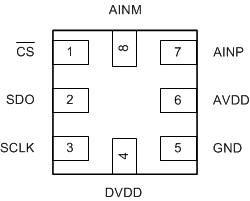
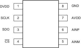
5 Pin Configuration and Functions


Pin Functions
| PIN | I/O | DESCRIPTION | ||
|---|---|---|---|---|
| NAME | NO. | |||
| RUG | DCU | |||
| AINM | 8 | 5 | Analog input | Analog signal input, negative |
| AINP | 7 | 6 | Analog input | Analog signal input, positive |
| AVDD | 6 | 7 | Supply | Analog power-supply input, also provides the reference voltage to the ADC |
| CS | 1 | 4 | Digital input | Chip-select signal, active low |
| DVDD | 4 | 1 | Supply | Digital I/O supply voltage |
| GND | 5 | 8 | Supply | Ground for power supply, all analog and digital signals are referred to this pin |
| SCLK | 3 | 2 | Digital input | Serial clock |
| SDO | 2 | 3 | Digital output | Serial data out |
6 Specifications
6.1 Absolute Maximum Ratings(1)
| MIN | MAX | UNIT | |
|---|---|---|---|
| AVDD to GND | –0.3 | 3.9 | V |
| DVDD to GND | –0.3 | 3.9 | V |
| AINP to GND | –0.3 | AVDD + 0.3 | V |
| AINM to GND | –0.3 | AVDD + 0.3 | V |
| Digital input voltage to GND | –0.3 | DVDD + 0.3 | V |
| Storage temperature, Tstg | –60 | 150 | °C |
6.2 ESD Ratings
| VALUE | UNIT | |||
|---|---|---|---|---|
| V(ESD) | Electrostatic discharge | Human body model (HBM), per ANSI/ESDA/JEDEC JS-001(1) | ±2000 | V |
| Charged device model (CDM), per JEDEC specification JESD22-C101(2) | ±1000 | |||
6.3 Recommended Operating Conditions
over operating free-air temperature range (unless otherwise noted)| MIN | MAX | UNIT | ||
|---|---|---|---|---|
| AVDD | Analog supply voltage range | 1.65 | 3.6 | V |
| DVDD | Digital supply voltage range | 1.65 | 3.6 | V |
| TA | Operating free-air temperature | –40 | 125 | °C |
6.4 Thermal Information
| THERMAL METRIC(1) | ADS7044 | UNIT | ||
|---|---|---|---|---|
| RUG (X2QFN) | DCU (VSSOP) | |||
| 8 PINS | 8 PINS | |||
| RθJA | Junction-to-ambient thermal resistance | 177.5 | 235.8 | °C/W |
| RθJC(top) | Junction-to-case (top) thermal resistance | 51.5 | 79.8 | °C/W |
| RθJB | Junction-to-board thermal resistance | 76.7 | 117.6 | °C/W |
| ψJT | Junction-to-top characterization parameter | 1.0 | 8.9 | °C/W |
| ψJB | Junction-to-board characterization parameter | 76.7 | 116.5 | °C/W |
| RθJC(bot) | Junction-to-case (bottom) thermal resistance | N/A | N/A | °C/W |
6.5 Electrical Characteristics
At TA = –40°C to 125°C, AVDD = 3 V, DVDD = 1.65 V to 3.6 V, fSAMPLE = 1 MSPS, unless otherwise noted.| PARAMETER | TEST CONDITIONS | MIN | TYP | MAX | UNIT | ||
|---|---|---|---|---|---|---|---|
| ANALOG INPUT | |||||||
| Full-scale input voltage span(1) | –AVDD | AVDD | V | ||||
| Absolute input voltage range | AINP to GND | –0.1 | AVDD + 0.1 | V | |||
| AINM to GND | –0.1 | AVDD + 0.1 | |||||
| CS | Sampling capacitance | 15 | pF | ||||
| SYSTEM PERFORMANCE | |||||||
| Resolution | 12 | Bits | |||||
| NMC | No missing codes | 12 | Bits | ||||
| INL | Integral nonlinearity | AVDD = 3 V | –1 | ±0.7 | 1 | LSB(2) | |
| AVDD = 1.8 V | –2 | ±1 | 2 | ||||
| DNL | Differential nonlinearity | AVDD = 3 V | –0.99 | ±0.5 | 1 | LSB | |
| AVDD = 1.8 V | –0.99 | ±0.7 | 2 | ||||
| EO | Uncalibrated offset error | AVDD = 1.65 V to 3.6 V | ±12 | LSB | |||
| Calibrated offset error(6) | AVDD = 3 V | –3 | ±0.5 | 3 | |||
| AVDD = 1.8 V | –4 | ±1 | 4 | ||||
| dVOS/dT | Offset error drift with temperature | 5 | ppm/°C | ||||
| EG | Gain error | AVDD = 3 V | –0.1 | ±0.05 | 0.1 | %FS | |
| AVDD = 1.8 V | –0.2 | ±0.1 | 0.2 | ||||
| Gain error drift with temperature | 2 | ppm/°C | |||||
| CMRR | Common-mode rejection ratio | fIN = 2 kHz, AVDD = 3 V | 53 | dB | |||
| SAMPLING DYNAMICS | |||||||
| tACQ | Acquisition time | 200 | ns | ||||
| Maximum throughput rate | 16-MHz SCLK, AVDD = 1.65 V to 3.6 V | 1 | MHz | ||||
| DYNAMIC CHARACTERISTICS | |||||||
| SNR | Signal-to-noise ratio(4) | fIN = 2 kHz, AVDD = 3 V | 70 | 71 | dB | ||
| fIN = 2 kHz, AVDD = 1.8 V | 70 | ||||||
| THD | Total harmonic distortion(4)(3) | fIN = 2 kHz, AVDD = 3 V | –85 | dB | |||
| SINAD | Signal-to-noise and distortion(4) | fIN = 2 kHz, AVDD = 3 V | 69.5 | 71 | dB | ||
| fIN = 2 kHz, AVDD = 1.8 V | 70 | ||||||
| SFDR | Spurious-free dynamic range(4) | fIN = 2 kHz, AVDD = 3 V | 85 | dB | |||
| BW(fp) | Full-power bandwidth | At –3 dB, AVDD = 3 V | 25 | MHz | |||
| DIGITAL INPUT/OUTPUT (CMOS Logic Family) | |||||||
| VIH | High-level input voltage(5) | 0.65 DVDD | DVDD + 0.3 | V | |||
| VIL | Low-level input voltage(5) | –0.3 | 0.35 DVDD | V | |||
| VOH | High-level output voltage(5) | At Isource = 500 µA | 0.8 DVDD | DVDD | V | ||
| At Isource = 2 mA | DVDD – 0.45 | DVDD | |||||
| VOL | Low-level output voltage(5) | At Isink = 500 µA | 0 | 0.2 DVDD | V | ||
| At Isink = 2 mA | 0 | 0.45 | |||||
| POWER-SUPPLY REQUIREMENTS | |||||||
| AVDD | Analog supply voltage | 1.65 | 3 | 3.6 | V | ||
| DVDD | Digital I/O supply voltage | 1.65 | 3 | 3.6 | V | ||
| IAVDD | Analog supply current | At 1 MSPS with AVDD = 3 V | 300 | µA | |||
| At 100 kSPS with AVDD = 3 V | 30 | ||||||
| At 1 MSPS with AVDD = 1.8 V | 145 | ||||||
| PD | Power dissipation | At 1 MSPS with AVDD = 3 V | 900 | µW | |||
| At 100 kSPS with AVDD = 3 V | 90 | ||||||
| At 1 MSPS with AVDD = 1.8 V | 261 | ||||||
6.6 Timing Characteristics
All specifications are at TA = –40°C to 125°C, AVDD = 1.65 V to 3.6 V, DVDD = 1.65 V to 3.6 V, and CLOAD on SDO = 20 pF, unless otherwise specified.6.7 Typical Characteristics
At TA = 25°C, AVDD = 3 V, DVDD = 1.8 V, and fSAMPLE = 1 MSPS, unless otherwise noted.
| SNR = 72.58 dB | THD = –93 dB | fIN = 2 kHz |
| Number of samples = 32768 | ||

| fIN = 2 kHz |


| AVDD = 3 V |

| AVDD = 1.8 V |


| AVDD = 1.8 V |

| SNR = 71.95 dB | THD = –76.5 dB | fIN = 250 kHz |
| Number of samples = 32768 | ||


| Mean code = 2046.98 | Sigma = 0.14 | |


| AVDD = 3 V |

| AVDD = 1.8 V |


| AVDD = 3 V |

7 Parameter Measurement Information
7.1 Digital Voltage Levels
The device complies with the JESD8-7A standard for DVDD from 1.65 V to 1.95 V. Figure 31 shows voltage levels for the digital input and output pins.
 Figure 31. Digital Voltage Levels as per the JESD8-7A Standard


