-
INA220-Q1 Automotive Grade, 26-V, Bi-Directional, Zero-Drift, Low- or High-Side, I2C-Compatible Current/Power Monitor
- 1 Features
- 2 Applications
- 3 Description
- 4 Revision History
- 5 Related Products
- 6 Pin Configuration and Functions
- 7 Specifications
-
8 Detailed Description
- 8.1 Overview
- 8.2 Functional Block Diagram
- 8.3 Feature Description
- 8.4 Device Functional Modes
- 8.5 Programming
- 8.6 Register Maps
- 9 Application and Implementation
- 10Power Supply Recommendations
- 11Layout
- 12Device and Documentation Support
- 13Mechanical, Packaging, and Orderable Information
- IMPORTANT NOTICE
Package Options
Mechanical Data (Package|Pins)
- DGS|10
Thermal pad, mechanical data (Package|Pins)
Orderable Information
INA220-Q1 Automotive Grade, 26-V, Bi-Directional, Zero-Drift, Low- or High-Side, I2C-Compatible Current/Power Monitor
1 Features
- Qualified for Automotive Applications
- AEC-Q100 Qualified with the following results:
- Device Temperature Grade 1: –40°C to +125°C Ambient Operating Temperature Range
- Device HBM ESD Classification Level H2
- Device CDM ESD Classification Level C3B
- High- or Low-Side Sensing
- Senses Bus Voltages from 0 V to 26 V
- Reports Current, Voltage, and Power
- 16 Programmable Addresses
- High Accuracy: 0.5% (Maximum) Over Temperature
- User-Programmable Calibration
- Fast (2.56-MHz) I2C- or SMBUS-Compatible Interface
- VSSOP-10 Package
2 Applications
- Electric Power Steering (EPS) Systems
- Body Control Modules
- Brake Systems
- Electronic Stability Control (ESC) Systems
3 Description
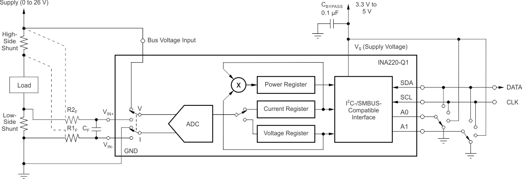
The INA220-Q1 device is a current shunt and power monitor with an I2C- or SMBUS-compatible interface. The INA220-Q1 device monitors both shunt drop and supply voltage. A programmable calibration value, combined with an internal multiplier, enables direct readouts in amperes. An additional multiplying register calculates power in watts. The I2C- or SMBUS-compatible interface features 16 programmable addresses. The separate shunt input on the INA220-Q1 device allows it to be used in systems with low-side sensing.
The INA220-Q1 device senses across shunts on buses that can vary from 0 to 26 V, useful for low-side sensing or CPU power supplies. The device uses a single 3- to 5.5-V supply, drawing a maximum of 1 mA of supply current. The INA220-Q1 device operates from –40°C to +125°C.
Device Information(1)
| PART NUMBER | PACKAGE | BODY SIZE (NOM) |
|---|---|---|
| INA220-Q1 | VSSOP (10) | 3.00 mm × 3.00 mm |
- For all available packages, see the orderable addendum at the end of the data sheet.
4 Revision History
Changes from A Revision (June 2012) to B Revision
- Changed part number to INA220-Q1Go
- Added ESD Ratings table, Feature Description section, Device Functional Modes section, Application and Implementation section, Power Supply Recommendations section, Layout section, Device and Documentation Support section, and Mechanical, Packaging, and Orderable Information section Go
- Changed "Two-wire" to "I2C- or SMBUS-compatible" throughout documentGo
- Deleted the Ordering Information table Go
- Corrected errors in graphicsGo
- Added automotive part numbers to Related ProductsGo
- Changed pin names in Pin Configuration and Functions Go
- Added common-mode definition to Absolute Maximum Ratings Go
- Changed IN+ and IN– pin input impedance to input bias current Go
- Changed Power register to Bus Voltage register Go
- Replaced Programming the INA220B-Q1 with Programming the INA220-Q1 Calibration RegisterGo
- Replaced PROGRAMMING THE INA220 POWER MEASUREMENT ENGINE with Calibration Register and ScalingGo
- Updated Table 2 based on one-time sample of devicesGo
- Changed Power register to Bus Voltage register Go
- Corrected register values in Detailed Design Procedure and Table 8Go
- Changed Configure, Measure, and Calculate Example table to Table 8 and removed first columnGo
Changes from * Revision (June 2012) to A Revision
- Device went from preview to productionGo
5 Related Products
| PART NUMBER | DESCRIPTION |
|---|---|
| INA212-Q1 | Automotive, 26-V, Bi-Directional, Zero-Drift, Precision, Low-/High-Side, Volt. Out Current Sense Amp |
| INA225-Q1 | Automotive, 36-V Prog. Gain, Bi-Directional, Zero-Drift, High-Speed Voltage Out Current Sense Amp |
| INA226-Q1 | Automotive, 36-V, Ultra-High Accuracy, Low-/High-Side, I2C Out Current/Power Monitor w/ Alert |
| INA282-Q1 | Automotive, 80-V, Bi-Directional, High Accuracy, Low-/High-Side, Voltage Out Current Shunt Monitor |
| INA300-Q1 | Automotive, 36-V Low-/High-Side, Overcurrent Protection Comparator |
| INA3221-Q1 | Automotive 26-V, Triple, Bi-Directional, Zero-Drift, I2C Out Current/Voltage Monitor w/ Alerts |
6 Pin Configuration and Functions

Pin Functions
| PIN | I/O | DESCRIPTION | |
|---|---|---|---|
| NO. | NAME | ||
| 1 | A1 | Digital Input | Address pin. Connect to GND, SCL, SDA, or VS. Table 1 shows pin settings and corresponding addresses. |
| 2 | A0 | Digital Input | Address pin. Connect to GND, SCL, SDA, or VS. Table 1 shows pin settings and corresponding addresses. |
| 3 | NC | — | No internal connection |
| 4 | SDA | Digital I/O | Serial bus data line |
| 5 | SCL | Digital Input | Serial bus clock line |
| 6 | VS | Analog | Power supply, 3 V to 5.5 V |
| 7 | GND | Analog | Ground |
| 8 | VBUS | Analog Input | Bus voltage input |
| 9 | IN– | Analog Input | Negative differential shunt voltage. Connect to negative side of shunt resistor. Bus voltage is measured from this pin to ground. |
| 10 | IN+ | Analog Input | Positive differential shunt voltage. Connect to positive side of shunt resistor. |
