-
ISO733x Robust EMC, Low Power, Triple-Channel Digital Isolators
- 1 Features
- 2 Applications
- 3 Description
- 4 Revision History
- 5 Pin Configuration and Functions
- 6 Specifications
- 7 Parameter Measurement Information
- 8 Detailed Description
- 9 Applications and Implementation
- 10Power Supply Recommendations
- 11Layout
- 12Device and Documentation Support
- 13Mechanical, Packaging, and Orderable Information
- IMPORTANT NOTICE
Package Options
Mechanical Data (Package|Pins)
- DW|16
Thermal pad, mechanical data (Package|Pins)
- DW|16
Orderable Information
ISO733x Robust EMC, Low Power, Triple-Channel Digital Isolators
1 Features
- Signaling Rate: 25 Mbps
- Integrated Noise Filter on the Inputs
- Default Output 'High' and 'Low' Options
- Low Power Consumption: Typical ICC per Channel at 1 Mbps:
- ISO7330: 1 mA (5 V Supplies),
0.8 mA (3.3 V Supplies) - ISO7331: 1.4 mA (5 V Supplies),
1 mA (3.3 V Supplies)
- ISO7330: 1 mA (5 V Supplies),
- Low Propagation Delay: 32 ns
Typical (5V Supplies) - Operates from 3.3 V and 5 V Supplies
- 3.3 V and 5 V Level Translation
- Wide Temperature Range: –40°C to 125°C
- 70 KV/μs Transient Immunity,
Typical (5V Supplies) - Robust Electromagnetic Compatibility (EMC)
- System-level ESD, EFT, and Surge Immunity
- Low Emissions
- Wide Body SOIC-16 Package
- Isolation Barrier Life: > 25 Years
- Safety and Regulatory Approvals:
2 Applications
- Opto-Coupler Replacement in:
- Industrial FieldBus
- ProfiBus
- ModBus
- DeviceNet™ Data Buses
- Servo Control Interface
- Motor Control
- Power Supplies
- Battery Packs
- Industrial FieldBus
3 Description
ISO733x provide galvanic isolation up to 3000 VRMS for 1 minute per UL and 4242 VPK per VDE. These devices have three isolated channels comprised of logic input and output buffers separated by a silicon dioxide (SiO2) insulation barrier. ISO7330 has all three channels in the same direction while ISO7331 has two channels in forward and one channel in reverse direction. In case of input power or signal loss, default output is 'low' for devices with suffix 'F' and 'high' for devices without suffix 'F'. Used in conjunction with isolated power supplies, these devices prevent noise currents on a data bus or other circuits from entering the local ground and interfering with or damaging sensitive circuitry. ISO733x has integrated noise filter for harsh industrial environment where short noise pulses may be present at the device input pins. ISO733x has TTL input thresholds and operates from 3 V to 5.5 V supply levels. Through innovative chip design and layout techniques, electromagnetic compatibility of ISO733x has been significantly enhanced to enable system-level ESD, EFT, Surge and Emissions compliance.
Device Information(1)
| PART NUMBER | PACKAGE | BODY SIZE (NOM) |
|---|---|---|
| ISO7330C | SOIC (16) | 10,3mm x 7,5mm |
| ISO7330FC | ||
| ISO7331C | ||
| ISO7331FC |
- For all available packages, see the orderable addendum at the end of the datasheet.
4 Revision History
Changes from A Revision (April 2015) to B Revision
- Changed "(VDE V 0884-10):2006-12" To "and DIN EN 61010-1" in the 4242 VPK in the FeaturesGo
- Changed From: VCCI To: VCC in Figure 12Go
- Deleted IEC from the section title: Package Insulation SpecificationsGo
- Changed the CTI Test Conditions in Package Insulation SpecificationsGo
- Changed VISO Test Condition in the Insulation Characteristics table Go
- Deleted the VISO Specification 3600 in the Insulation Characteristics table Go
Changes from * Revision (January 2015) to A Revision
- Changed the device From: Product Preview To: Production data Go
- Changed Features From: ISO7330: TBD mA To: 1 mAGo
- Changed Features From: ISO731: TBD mA (3.3 V Supplies) To: 0.8 mAGo
- Changed Features From: ISO731: TBD mA (5 V Supplies) To: 1.4 mAGo
- Changed Features From: 65 KV/μs Transient Immunity To: 70 KV/μs Transient ImmunityGo
- Changed the Safety and Regulatory Approvals FeaturesGo
- Changed the Simplified Schematic and added Notes 1 and 2Go
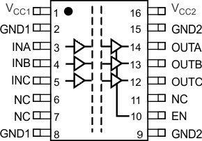
5 Pin Configuration and Functions


Pin Functions
| PIN | I/O | DESCRIPTION | ||
|---|---|---|---|---|
| NAME | ISO7330 | ISO7331 | ||
| VCC1 | 1 | 1 | – | Power supply, VCC1 |
| VCC2 | 16 | 16 | – | Power supply, VCC2 |
| GND1 | 2, 8 | 2, 8 | – | Ground connection for VCC1 |
| GND2 | 9, 15 | 9, 15 | – | Ground connection for VCC2 |
| INA | 3 | 3 | I | Input, channel A |
| INB | 4 | 4 | I | Input, channel B |
| INC | 5 | 12 | I | Input, channel C |
| NC | 6, 7, 11 | 6, 11 | – | No Connect. These pins have no internal connection. |
| OUTA | 14 | 14 | O | Output, channel A |
| OUTB | 13 | 13 | O | Output, channel B |
| OUTC | 12 | 5 | O | Output, channel C |
| EN | 10 | – | I | Output enable. OUTA, OUTB, and OUTC are enabled when EN is high or disconnected and disabled when EN is low. |
| EN1 | – | 7 | I | Output enable 1. OUTC is enabled when EN1 is high or disconnected and disabled when EN1 is low. |
| EN2 | – | 10 | I | Output enable 2. OUTA and OUTB are enabled when EN2 is high or disconnected and disabled when EN2 is low. |
