SBAS740B October 2015 – May 2020 ADS1118-Q1
PRODUCTION DATA.
- 1 Features
- 2 Applications
- 3 Description
- 4 Revision History
- 5 Device Comparison Table
- 6 Pin Configuration and Functions
- 7 Specifications
- 8 Parameter Measurement Information
- 9 Detailed Description
- 10Application and Implementation
- 11Power Supply Recommendations
- 12Layout
- 13Device and Documentation Support
- 14Mechanical, Packaging, and Orderable Information
10.1.1 Serial Interface Connections
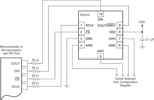
The principle serial interface connections for the ADS1118-Q1 are shown in Figure 39.
 Figure 39. Typical Connections
 Most microcontroller SPI peripherals operate with the ADS1118-Q1. The interface operates in SPI mode 1 where CPOL = 0 and CPHA = 1, SCLK idles low, and data are launched or changed only on SCLK rising edges; data are latched or read by the master and slave on SCLK falling edges. Details of the SPI communication protocol employed by the ADS1118-Q1 can be found in the Timing Requirements: Serial Interface section.
It is a good practice to place 50-Ω resistors in the series path to each of the digital pins to provide some short-circuit protection. Take care to still meet all SPI timing requirements because these additional series resistors along with the bus parasitic capacitances present on the digital signal lines slews the signals.
The fully-differential input of the ADS1118-Q1 is ideal for connecting to differential sources (such as thermocouples and thermistors) with a moderately low source impedance. Although the ADS1118-Q1 can read fully-differential signals, the device cannot accept negative voltages on either of its inputs because of ESD protection diodes on each pin. When an input exceeds supply or drops below ground, these diodes turn on to prevent any ESD damage to the device.