JAJSDU5A August 2017 – February 2020 ADS114S06B , ADS114S08B
PRODUCTION DATA.
- 1 特長
- 2 アプリケーション
- 3 概要
- 4 改訂履歴
- 5 Device Comparison Table
- 6 Pin Configuration and Functions
- 7 Specifications
- 8 Parameter Measurement Information
-
9 Detailed Description
- 9.1 Overview
- 9.2 Functional Block Diagram
- 9.3
Feature Description
- 9.3.1 Multiplexer
- 9.3.2 Low-Noise Programmable Gain Amplifier
- 9.3.3 Voltage Reference
- 9.3.4 Clock Source
- 9.3.5 Delta-Sigma Modulator
- 9.3.6 Digital Filter
- 9.3.7 Excitation Current Sources (IDACs)
- 9.3.8 Bias Voltage Generation
- 9.3.9 System Monitor
- 9.3.10 Status Register
- 9.3.11 General-Purpose Inputs and Outputs (GPIOs)
- 9.3.12 Calibration
- 9.4 Device Functional Modes
- 9.5 Programming
- 9.6
Register Map
- 9.6.1 Configuration Registers
- 9.6.2
Register Descriptions
- 9.6.2.1 Device ID Register (address = 00h) [reset = xxh]
- 9.6.2.2 Device Status Register (address = 01h) [reset = 80h]
- 9.6.2.3 Input Multiplexer Register (address = 02h) [reset = 01h]
- 9.6.2.4 Gain Setting Register (address = 03h) [reset = 00h]
- 9.6.2.5 Data Rate Register (address = 04h) [reset = 14h]
- 9.6.2.6 Reference Control Register (address = 05h) [reset = 10h]
- 9.6.2.7 Excitation Current Register 1 (address = 06h) [reset = 00h]
- 9.6.2.8 Excitation Current Register 2 (address = 07h) [reset = FFh]
- 9.6.2.9 Sensor Biasing Register (address = 08h) [reset = 00h]
- 9.6.2.10 System Control Register (address = 09h) [reset = 10h]
- 9.6.2.11 Reserved Register (address = 0Ah) [reset = 00h]
- 9.6.2.12 Offset Calibration Register 1 (address = 0Bh) [reset = 00h]
- 9.6.2.13 Offset Calibration Register 2 (address = 0Ch) [reset = 00h]
- 9.6.2.14 Reserved Register (address = 0Dh) [reset = 00h]
- 9.6.2.15 Gain Calibration Register 1 (address = 0Eh) [reset = 00h]
- 9.6.2.16 Gain Calibration Register 2 (address = 0Fh) [reset = 40h]
- 9.6.2.17 GPIO Data Register (address = 10h) [reset = 00h]
- 9.6.2.18 GPIO Configuration Register (address = 11h) [reset = 00h]
- 10Application and Implementation
- 11Power Supply Recommendations
- 12Layout
- 13デバイスおよびドキュメントのサポート
- 14メカニカル、パッケージ、および注文情報
パッケージ・オプション
デバイスごとのパッケージ図は、PDF版データシートをご参照ください。
メカニカル・データ(パッケージ|ピン)
- RHB|32
- PBS|32
サーマルパッド・メカニカル・データ
- PBS|32
発注情報
9.3.2 Low-Noise Programmable Gain Amplifier
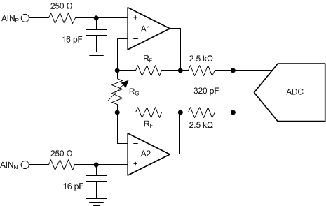
The ADS114S06B and ADS114S08B feature a low-drift, low-noise, high input impedance programmable gain amplifier (PGA). Figure 43 shows a simplified diagram of the PGA. The PGA consists of two chopper-stabilized amplifiers (A1 and A2) and a resistor feedback network that sets the gain of the PGA. The PGA input is equipped with an electromagnetic interference (EMI) filter and an antialiasing filter on the output.
 Figure 43. Simplified PGA Diagram
 The PGA can be set to gains of 1, 2, 4, 8, 16, 32, 64, or 128 using the GAIN[2:0] bits in the gain setting register (03h). Gain is changed inside the device using a variable resistor, RG. The differential full-scale input voltage range (FSR) of the PGA is defined by the gain setting and the reference voltage used, as shown in Equation 4:
Table 3 shows the corresponding full-scale ranges when using the internal 2.5-V reference.
Table 3. PGA Full-Scale Range
| GAIN SETTING | FSR |
|---|---|
| 1 | ±2.5 V |
| 2 | ±1.25 V |
| 4 | ±0.625 V |
| 8 | ±0.313 V |
| 16 | ±0.156 V |
| 32 | ±0.078 V |
| 64 | ±0.039 V |
| 128 | ±0.020 V |
The PGA must be enabled with the PGA_EN[1:0] bits of the gain setting register (03h). Setting these bits to 00 powers down and bypasses the PGA. A setting of 01 enables the PGA. The 10 and 11 settings are reserved and must not be written to the device.
With the PGA enabled, gains 64 and 128 are established in the digital domain. When the device is set to 64 or 128, the PGA is set to a gain of 32, and additional gain is established with digital scaling. The input-referred noise does still improve compared to the gain = 32 setting because the PGA is biased with a higher supply current to reduce noise.