JAJSDU5A August 2017 – February 2020 ADS114S06B , ADS114S08B
PRODUCTION DATA.
- 1 特長
- 2 アプリケーション
- 3 概要
- 4 改訂履歴
- 5 Device Comparison Table
- 6 Pin Configuration and Functions
- 7 Specifications
- 8 Parameter Measurement Information
-
9 Detailed Description
- 9.1 Overview
- 9.2 Functional Block Diagram
- 9.3
Feature Description
- 9.3.1 Multiplexer
- 9.3.2 Low-Noise Programmable Gain Amplifier
- 9.3.3 Voltage Reference
- 9.3.4 Clock Source
- 9.3.5 Delta-Sigma Modulator
- 9.3.6 Digital Filter
- 9.3.7 Excitation Current Sources (IDACs)
- 9.3.8 Bias Voltage Generation
- 9.3.9 System Monitor
- 9.3.10 Status Register
- 9.3.11 General-Purpose Inputs and Outputs (GPIOs)
- 9.3.12 Calibration
- 9.4 Device Functional Modes
- 9.5 Programming
- 9.6
Register Map
- 9.6.1 Configuration Registers
- 9.6.2
Register Descriptions
- 9.6.2.1 Device ID Register (address = 00h) [reset = xxh]
- 9.6.2.2 Device Status Register (address = 01h) [reset = 80h]
- 9.6.2.3 Input Multiplexer Register (address = 02h) [reset = 01h]
- 9.6.2.4 Gain Setting Register (address = 03h) [reset = 00h]
- 9.6.2.5 Data Rate Register (address = 04h) [reset = 14h]
- 9.6.2.6 Reference Control Register (address = 05h) [reset = 10h]
- 9.6.2.7 Excitation Current Register 1 (address = 06h) [reset = 00h]
- 9.6.2.8 Excitation Current Register 2 (address = 07h) [reset = FFh]
- 9.6.2.9 Sensor Biasing Register (address = 08h) [reset = 00h]
- 9.6.2.10 System Control Register (address = 09h) [reset = 10h]
- 9.6.2.11 Reserved Register (address = 0Ah) [reset = 00h]
- 9.6.2.12 Offset Calibration Register 1 (address = 0Bh) [reset = 00h]
- 9.6.2.13 Offset Calibration Register 2 (address = 0Ch) [reset = 00h]
- 9.6.2.14 Reserved Register (address = 0Dh) [reset = 00h]
- 9.6.2.15 Gain Calibration Register 1 (address = 0Eh) [reset = 00h]
- 9.6.2.16 Gain Calibration Register 2 (address = 0Fh) [reset = 40h]
- 9.6.2.17 GPIO Data Register (address = 10h) [reset = 00h]
- 9.6.2.18 GPIO Configuration Register (address = 11h) [reset = 00h]
- 10Application and Implementation
- 11Power Supply Recommendations
- 12Layout
- 13デバイスおよびドキュメントのサポート
- 14メカニカル、パッケージ、および注文情報
パッケージ・オプション
デバイスごとのパッケージ図は、PDF版データシートをご参照ください。
メカニカル・データ(パッケージ|ピン)
- RHB|32
- PBS|32
サーマルパッド・メカニカル・データ
- PBS|32
発注情報
9.3.6 Digital Filter
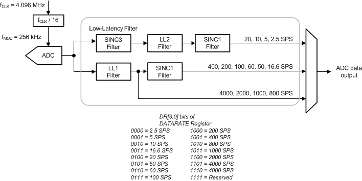
The devices offer digital filter options for decimation of the digital data stream coming from the delta-sigma modulator. The implementation of the digital filter is determined by the data rate setting. Figure 46 shows the digital filter implementation.
The low-latency digital filter is a finite impulse response (FIR) filter that provides settled data, given that the analog input signal has settled to the final value before the conversion is started. This digital filter implementation is especially useful when multiple channels must be scanned in minimal time.

NOTE:
LL filter = low-latency filter.The device requires a set number of modulator clocks to output a single ADC conversion data. This number is known as the oversampling ratio (OSR). The OSR of the digital filter is set using the DR[3:0] bits in the data rate register. Equation 8 determines the data rate.
Table 5 shows the relationship between the data rate and oversampling ratio.
Table 5. ADC Data Rates and Digital Filter Oversampling Ratios
| NOMINAL DATA RATE
(SPS)(1) |
DATA RATE REGISTER
DR[3:0] |
OVERSAMPLING
RATIO(2) |
|---|---|---|
| 2.5 | 0000 | 102400 |
| 5 | 0001 | 51200 |
| 10 | 0010 | 25600 |
| 16.6 | 0011 | 15360 |
| 20 | 0100 | 12800 |
| 50 | 0101 | 5120 |
| 60 | 0110 | 4264 |
| 100 | 0111 | 2560 |
| 200 | 1000 | 1280 |
| 400 | 1001 | 640 |
| 800 | 1010 | 320 |
| 1000 | 1011 | 256 |
| 2000 | 1100 | 128 |
| 4000 | 1101 | 64 |