JAJSHL9A June 2019 – January 2021 ADS125H01
PRODUCTION DATA
- 1 特長
- 2 アプリケーション
- 3 概要
- 4 Revision History
- 5 Device Comparison Table
- 6 Pin Configuration and Functions
- 7 Specifications
- 8 Parameter Measurement Information
-
9 Detailed Description
- 9.1 Overview
- 9.2 Functional Block Diagram
- 9.3 Feature Description
- 9.4 Device Functional Modes
- 9.5 Programming
- 9.6
Register Map
- 9.6.1 Device Identification (ID) Register (address = 00h) [reset = 4xh]
- 9.6.2 Main Status (STATUS0) Register (address = 01h) [reset = 01h]
- 9.6.3 Mode 0 (MODE0) Register (address = 02h) [reset = 24h]
- 9.6.4 Mode 1 (MODE1) Register (address = 03h) [reset = 01h]
- 9.6.5 Reserved (RESERVED) Register (address = 04h) [reset = 00h]
- 9.6.6 Mode 3 (MODE3) Register (address = 05h) [reset = 00h]
- 9.6.7 Reference Configuration (REF) Register (address = 06h) [reset = 05h]
- 9.6.8 Offset Calibration (OFCALx) Registers (address = 07h, 08h, 09h) [reset = 00h, 00h, 00h]
- 9.6.9 Full-Scale Calibration (FSCALx) Registers (address = 0Ah, 0Bh, 0Ch) [reset = 00h, 00h, 40h]
- 9.6.10 Reserved (RESERVED) Register (address = 0Dh) [reset = FFh]
- 9.6.11 Reserved (RESERVED) Register (address = 0Eh) [reset = 00h]
- 9.6.12 Reserved (RESERVED) Register (address = 0Fh) [reset = 00h]
- 9.6.13 MODE4 (MODE4) Register (address = 10h) [reset = 50h]
- 9.6.14 PGA Alarm (STATUS1) Register (address = 11h) [reset = xxh]
- 9.6.15 Status 2 (STATUS2) Register (address = 12h) [reset = 0xh]
- 10Application and Implementation
- 11Power Supply Recommendations
- 12Layout
- 13Device and Documentation Support
- 14Mechanical, Packaging, and Orderable Information
パッケージ・オプション
メカニカル・データ(パッケージ|ピン)
- RHB|32
サーマルパッド・メカニカル・データ
- RHB|32
発注情報
9.3.6.2 FIR Filter
The finite impulse response (FIR) filter provides simultaneous rejection of 50-Hz and 60-Hz line cycle frequencies and related harmonics at data rates of 2.5 SPS, 5 SPS, 10 SPS, and 20 SPS. The conversion latency of the FIR filter is a single cycle; see Table 9-6 for detailed latency values. As illustrated in Figure 9-6, the FIR filter section receives data from the second-stage sinc filter. The FIR filter section decimates the data to yield the output data rate of 20 SPS. A variable averaging filter (sinc1) yields 10 SPS, 5 SPS, and 2.5 SPS.
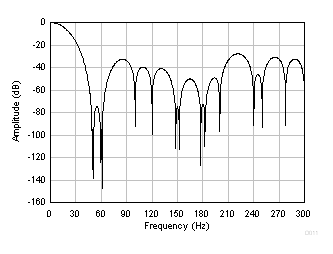
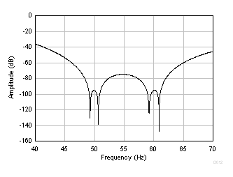
As shown in Figure 9-15 and Figure 9-16, the frequency response has nulls that are positioned near 50 Hz and 60 Hz.
 Figure 9-15 FIR Filter Frequency
Response (20 SPS)
 Figure 9-16 FIR Filter Frequency
Response Detail (20 SPS)
Figure 9-16 FIR Filter Frequency
Response Detail (20 SPS)Similar to the response of the sinc filter, the overall FIR filter frequency has a low-pass response that rolls off high frequencies. The signal bandwidth depends on the output data rate. Table 9-4 lists the –3-dB filter bandwidth of the FIR filter. The total system bandwidth is the combined response of the digital filter, the PGA antialias filter, and external filters.
| DATA RATE (SPS) | –3-dB BANDWIDTH (Hz) |
|---|---|
| 2.5 | 1.2 |
| 5 | 2.4 |
| 10 | 4.7 |
| 20 | 13 |