JAJSHV5B June 2017 – August 2019 ADS1287
PRODUCTION DATA.
- 1 特長
- 2 アプリケーション
- 3 概要
- 4 改訂履歴
- 5 概要(続き)
- 6 Pin Configuration and Functions
- 7 Specifications
- 8 Parameter Measurement Information
-
9 Detailed Description
- 9.1 Overview
- 9.2 Functional Block Diagram
- 9.3 Feature Description
- 9.4 Device Functional Modes
- 9.5
Programming
- 9.5.1 Serial Interface
- 9.5.2
Commands
- 9.5.2.1 WAKEUP: Wake Up Command
- 9.5.2.2 STANDBY: Standby Mode Command
- 9.5.2.3 SYNC: Synchronize ADC Conversions
- 9.5.2.4 RESET: Reset Command
- 9.5.2.5 RDATAC: Read Data Continuous Mode Command
- 9.5.2.6 SDATAC: Stop Read Data Continuous Mode Command
- 9.5.2.7 RDATA: Read Data Command
- 9.5.2.8 RREG: Read Register Data Command
- 9.5.2.9 WREG: Write Register Data Command
- 9.5.2.10 OFSCAL: Offset Calibration Command
- 9.5.2.11 GANCAL: Gain Calibration Command
- 9.6
Register Map
- 9.6.1
Register Descriptions
- 9.6.1.1 ID/CFG: ID, Configuration Register (address = 00h) [reset = x0h]
- 9.6.1.2 CONFIG0: Configuration Register 0 (address = 01h) [reset = 52h]
- 9.6.1.3 CONFIG1: Configuration Register 1 (address = 02h) [reset = 08h]
- 9.6.1.4 High-Pass Filter Corner Frequency (HPFx) Registers (address = 03h, 04h) [reset = 32h, 03h]
- 9.6.1.5 Offset Calibration (OFCx) Registers (address = 05h, 06h, 07h) [reset = 00h, 00h, 00h]
- 9.6.1.6 Full-Scale Calibration (FSCx) Registers (address = 08h, 09h, 0Ah) [reset = 00h, 00h, 40h]
- 9.6.1
Register Descriptions
- 10Application and Implementation
- 11Power Supply Recommendations
- 12Layout
- 13デバイスおよびドキュメントのサポート
- 14メカニカル、パッケージ、および注文情報
パッケージ・オプション
デバイスごとのパッケージ図は、PDF版データシートをご参照ください。
メカニカル・データ(パッケージ|ピン)
- RHF|24
サーマルパッド・メカニカル・データ
発注情報
9.3.5.4 HPF Stage
The last stage of the digital filter is a high-pass filter (HPF) implemented as a first-order, IIR structure. This filter stage blocks DC signals and rolls off low-frequency components below the cutoff frequency. Equation 10 shows the transfer function for the filter:

The high-pass filter corner frequency is programmed by the HPF[1:0] register bits, in hexadecimal. Equation 12 is used to set the high-pass filter corner frequency. Table 12 lists example values for the high-pass filter.

where
- HPF = High-pass filter register value (converted to hexadecimal)
- ωN = 2πfHP / fDATA (normalized frequency, radians)
- fHP = High-pass filter corner frequency (Hz)
- fDATA = Data rate (Hz)
Table 12. High-Pass Filter Value Examples
| HPF1, HPF0 | fHP (Hz) | DATA RATE (SPS) |
|---|---|---|
| 0337h | 0.5 | 250 |
| 0337h | 1.0 | 500 |
| 019Ah | 1.0 | 1000 |
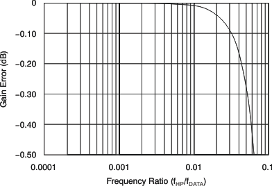
Equation 13 shows the HPF frequency domain transfer function. The HPF results in a small gain error that depends on the ratio of fHP / fDATA. For many common values of (fHP / fDATA), the gain error is negligible. Figure 56 shows the gain error of the HPF.
 Figure 56. HPF Gain Error
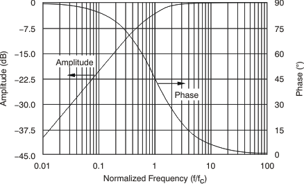
Figure 57 shows the first-order amplitude and phase response of the HPF. In the case of applied step input or after synchronizing, make sure to take the settling time of the filter into account.
 Figure 57. HPF Amplitude and Phase Response