JAJSNY5 August 2022 ADS131M03-Q1
PRODUCTION DATA
- 1 特長
- 2 アプリケーション
- 3 概要
- 4 Revision History
- 5 Pin Configuration and Functions
- 6 Specifications
- 7 Parameter Measurement Information
-
8 Detailed Description
- 8.1 Overview
- 8.2 Functional Block Diagram
- 8.3
Feature Description
- 8.3.1 Input ESD Protection Circuitry
- 8.3.2 Input Multiplexer
- 8.3.3 Programmable Gain Amplifier (PGA)
- 8.3.4 Voltage Reference
- 8.3.5 Clocking and Power Modes
- 8.3.6 ΔΣ Modulator
- 8.3.7 Digital Filter
- 8.3.8 DC Block Filter
- 8.3.9 Internal Test Signals
- 8.3.10 Channel Phase Calibration
- 8.3.11 Calibration Registers
- 8.3.12 Communication Cyclic Redundancy Check (CRC)
- 8.3.13 Register Map CRC
- 8.4 Device Functional Modes
- 8.5
Programming
- 8.5.1
Interface
- 8.5.1.1 Chip Select (CS)
- 8.5.1.2 Serial Data Clock (SCLK)
- 8.5.1.3 Serial Data Input (DIN)
- 8.5.1.4 Serial Data Output (DOUT)
- 8.5.1.5 Data Ready (DRDY)
- 8.5.1.6 Conversion Synchronization or System Reset (SYNC/RESET)
- 8.5.1.7 SPI Communication Frames
- 8.5.1.8 SPI Communication Words
- 8.5.1.9 ADC Conversion Data
- 8.5.1.10
Commands
- 8.5.1.10.1 NULL (0000 0000 0000 0000)
- 8.5.1.10.2 RESET (0000 0000 0001 0001)
- 8.5.1.10.3 STANDBY (0000 0000 0010 0010)
- 8.5.1.10.4 WAKEUP (0000 0000 0011 0011)
- 8.5.1.10.5 LOCK (0000 0101 0101 0101)
- 8.5.1.10.6 UNLOCK (0000 0110 0101 0101)
- 8.5.1.10.7 RREG (101a aaaa annn nnnn)
- 8.5.1.10.8 WREG (011a aaaa annn nnnn)
- 8.5.1.11 Short SPI Frames
- 8.5.2 Synchronization
- 8.5.1
Interface
- 8.6 ADS131M03-Q1 Registers
- 9 Application and Implementation
- 10Device and Documentation Support
- 11Mechanical, Packaging, and Orderable Information
5 Pin Configuration and Functions
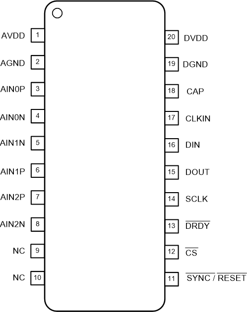
 Figure 5-1 PW Package,20-Pin TSSOP(Top View)
Table 5-1 Pin Functions
| PIN | I/O | DESCRIPTION(1) | |
|---|---|---|---|
| NAME | NO. | ||
| AGND | 2 | Supply | Analog ground |
| AIN0N | 4 | Analog input | Negative analog input 0 |
| AIN0P | 3 | Analog input | Positive analog input 0 |
| AIN1N | 5 | Analog input | Negative analog input 1 |
| AIN1P | 6 | Analog input | Positive analog input 1 |
| AIN2N | 8 | Analog input | Negative analog input 2 |
| AIN2P | 7 | Analog input | Positive analog input 2 |
| AVDD | 1 | Supply | Analog supply. Connect a 1-µF capacitor to AGND. |
| CAP | 18 | Analog output | Digital low-dropout (LDO) regulator output. Connect a 220-nF capacitor to DGND. |
| CLKIN | 17 | Digital input | Main clock input |
| CS | 12 | Digital input | Chip select; active low |
| DGND | 19 | Supply | Digital ground |
| DIN | 16 | Digital input | Serial data input |
| DOUT | 15 | Digital output | Serial data output |
| DRDY | 13 | Digital output | Data ready; active low |
| DVDD | 20 | Supply | Digital I/O supply. Connect a 1-µF capacitor to DGND. |
| NC | 9, 10 | — | Leave unconnected or connect to AGND |
| SCLK | 14 | Digital input | Serial data clock |
| SYNC/RESET | 11 | Digital input | Conversion synchronization or system reset; active low |
(1) See the Section 9.1.1 section for details on how to connect unused
pins.