JAJSNY5 August 2022 ADS131M03-Q1
PRODUCTION DATA
- 1 特長
- 2 アプリケーション
- 3 概要
- 4 Revision History
- 5 Pin Configuration and Functions
- 6 Specifications
- 7 Parameter Measurement Information
-
8 Detailed Description
- 8.1 Overview
- 8.2 Functional Block Diagram
- 8.3
Feature Description
- 8.3.1 Input ESD Protection Circuitry
- 8.3.2 Input Multiplexer
- 8.3.3 Programmable Gain Amplifier (PGA)
- 8.3.4 Voltage Reference
- 8.3.5 Clocking and Power Modes
- 8.3.6 ΔΣ Modulator
- 8.3.7 Digital Filter
- 8.3.8 DC Block Filter
- 8.3.9 Internal Test Signals
- 8.3.10 Channel Phase Calibration
- 8.3.11 Calibration Registers
- 8.3.12 Communication Cyclic Redundancy Check (CRC)
- 8.3.13 Register Map CRC
- 8.4 Device Functional Modes
- 8.5
Programming
- 8.5.1
Interface
- 8.5.1.1 Chip Select (CS)
- 8.5.1.2 Serial Data Clock (SCLK)
- 8.5.1.3 Serial Data Input (DIN)
- 8.5.1.4 Serial Data Output (DOUT)
- 8.5.1.5 Data Ready (DRDY)
- 8.5.1.6 Conversion Synchronization or System Reset (SYNC/RESET)
- 8.5.1.7 SPI Communication Frames
- 8.5.1.8 SPI Communication Words
- 8.5.1.9 ADC Conversion Data
- 8.5.1.10
Commands
- 8.5.1.10.1 NULL (0000 0000 0000 0000)
- 8.5.1.10.2 RESET (0000 0000 0001 0001)
- 8.5.1.10.3 STANDBY (0000 0000 0010 0010)
- 8.5.1.10.4 WAKEUP (0000 0000 0011 0011)
- 8.5.1.10.5 LOCK (0000 0101 0101 0101)
- 8.5.1.10.6 UNLOCK (0000 0110 0101 0101)
- 8.5.1.10.7 RREG (101a aaaa annn nnnn)
- 8.5.1.10.8 WREG (011a aaaa annn nnnn)
- 8.5.1.11 Short SPI Frames
- 8.5.2 Synchronization
- 8.5.1
Interface
- 8.6 ADS131M03-Q1 Registers
- 9 Application and Implementation
- 10Device and Documentation Support
- 11Mechanical, Packaging, and Orderable Information
9.1.3 Minimum Interface Connections
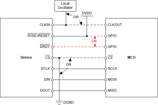
Figure 9-2 depicts how the ADS131M03-Q1 can be configured for the minimum number of interface pins. This configuration is useful when using data isolation to minimize the number of isolation channels required or when the microcontroller (MCU) pins are limited.
The CLKIN pin requires an LVCMOS clock that can be either generated by the MCU or created using a local LVCMOS output device. Tie the SYNC/RESET pin to DVDD in hardware if unused. The DRDY pin can be left floating if unused. Connect either SYNC/RESET or DRDY to the MCU to ensure the MCU stays synchronized to ADC conversions. If the MCU provides CLKIN, the CLKIN periods can be counted to determine the sample period rather than forcing synchronization using the SYNC/RESET pin or monitoring the DRDY pin. Synchronization cannot be regained if a bit error occurs on the clock and samples can be missed if the SYNC/RESET or DRDY pins are not used. CS can be tied low in hardware if the ADS131M03-Q1 is the only device on the SPI bus. Ensure the data input and output CRC are enabled and are used to guard against faulty register reads and writes if CS is tied low permanently.
 Figure 9-2 Minimum
Connections Required to Operate the ADS131M03-Q1